PRESS MAINTENANCE TIPS
.
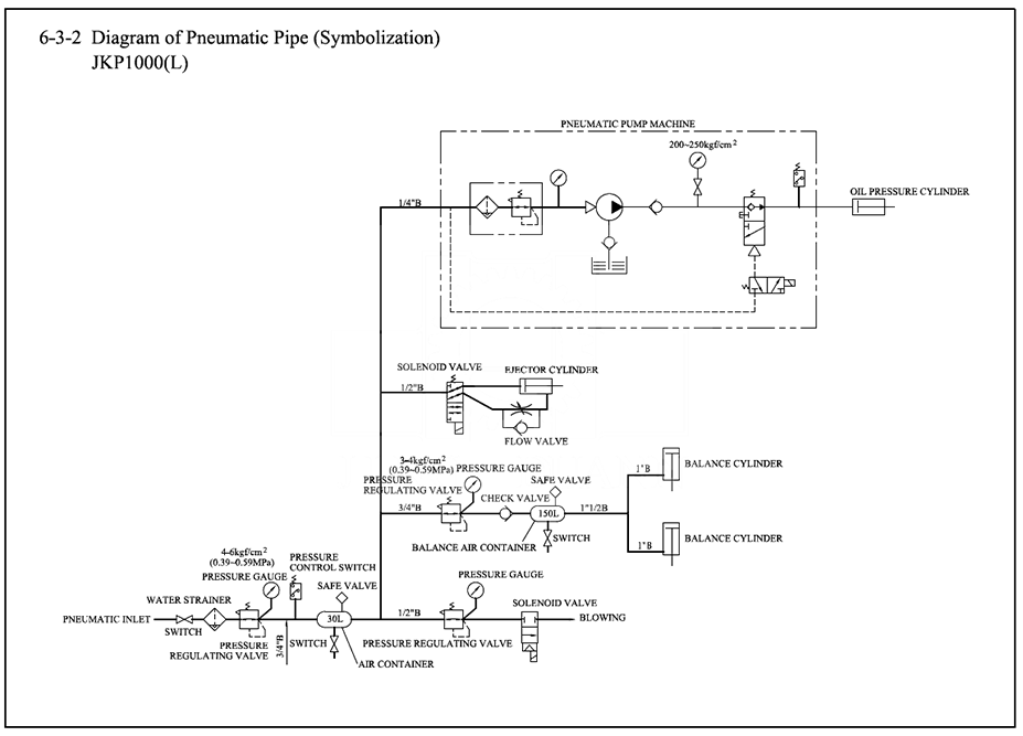
Air Systems Maintenance Tips
Fundamentals & Importance
Air Systems are a crucial part to mechanical presses and to a lesser degree to servo hydraulic presses. Safety for press operators depends on proper maintenance and operating systems. If any part of the air system is leaking or not functioning properly, it should be reported to maintenance supervisor immediately.
All presses should be equipped with a minimum of electronically monitored air pressure switch that will prevent press operation if air pressure is too low.
Failure to make sure air systems are operating and set to correct pressures can result in major damage to other parts of the press drive system (see #4 connection points).
√ Factory provided air to presses and equipment should be clean and dry which is not always the case.
√ A master air supply / lockable air dump valve should be in-line to connection to press.
√ Pressure regulators at press should be properly set to factory recommended pressures.
√ Maintenance staff should refer to air system schematic to be sure they are checking all systems.
√ No Leak condition throughout air system should be verified during routine maintenance.
√ Air Supply storage tanks should be drained weekly of any condensation or moisture.
Items that could be on your press depending on type of press:
• Air supply tanks (secure and no leak condition)
• Air supply tanks drains to prevent downstream component contamination
• In-line filters, lubricators, pressure regulators & pressure switches
• Quick connect outlets for connection of air tools
• Dual valve for clutch and brake with muffler to activate CB unit (see #3 CB tips)
• Rotary air inlet joint at CB unit
• Flywheel brake
• Slide locking systems on hydraulic presses
• HOLP / Air over hydraulic overload system, and pump (see #7 HOLP tips)
• Air counterbalance systems (see #2 ACB tips)
• Air-line hoses and connection fittings
Click here for free Press Terminology document
.
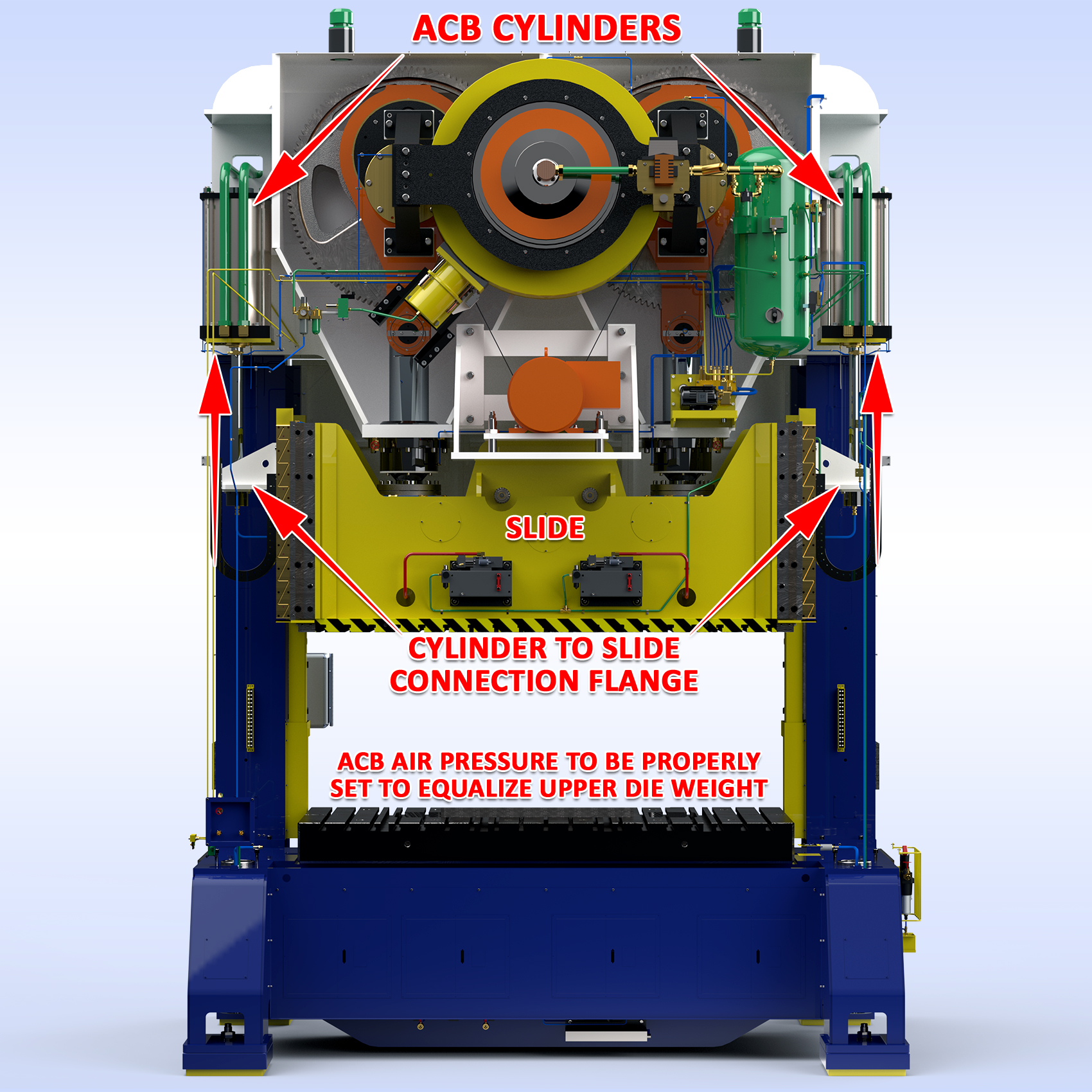
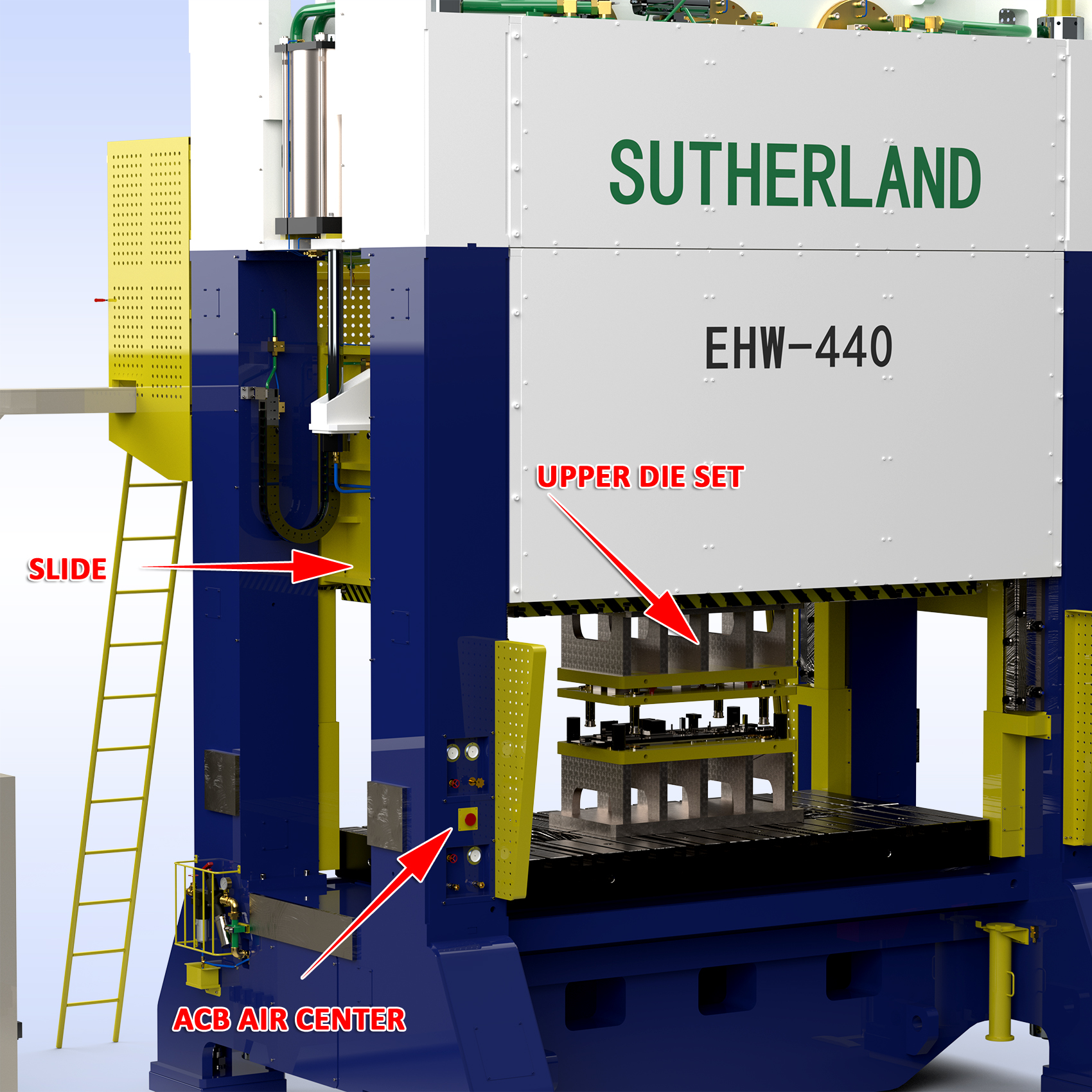
ACB / Air Counter-Balance Systems
Fundamentals & Importance
Air Counter-Balance Systems are a crucial part to mechanical presses. If any part of the air system is leaking or not functioning properly, it should be reported to maintenance supervisor immediately.
All presses should be equipped with an ACB pressure gage, adjustment regulator and a graph chart that indicates air pressure required to upper die weight. Each time a new die is loaded the ACB pressure should be reset. Good practice is to mark upper die to show correct measured weight.
Failure to make sure ACB system is set to correct pressures will result in major damage to other parts of the press drive system (see #4 connection points).
√ ACB Systems are the most overlooked & improperly used systems on stamping presses.
√ Never open ACB cylinders unless all air is drained from press and apply lock out / tag out rules.
√ Understand the difference of static load (slide not moving) and dynamic load (slide moving) to set proper ACB pressure. Faster strokes per minute will require increase in air pressure to account for the mass / weight and speed of slide. If your press is equipped with a main motor AMP draw indicator, this is the best way to assure proper ACB pressures for the speed you are running the press. Too much pressure = AMP increase on down stroke, Too little pressure = AMP increase on up stroke.
√ Properly set ACB pressure allows good lubrication flow to all bearings and bushings in the drive.
√ Too low pressure will cause a jack hammer effect on all bearings, bushings and drive gears.
√ Maintenance should be sure to drain ACB air supply tank weekly to remove any moisture.
√ Inspect lubrication to ACB cylinders to make sure seals and packings are properly lubricated.
√ Inspect ACB rods that connect cylinders to slide and make sure no scoring marks are present.
Click here for more ACB Tips.
.
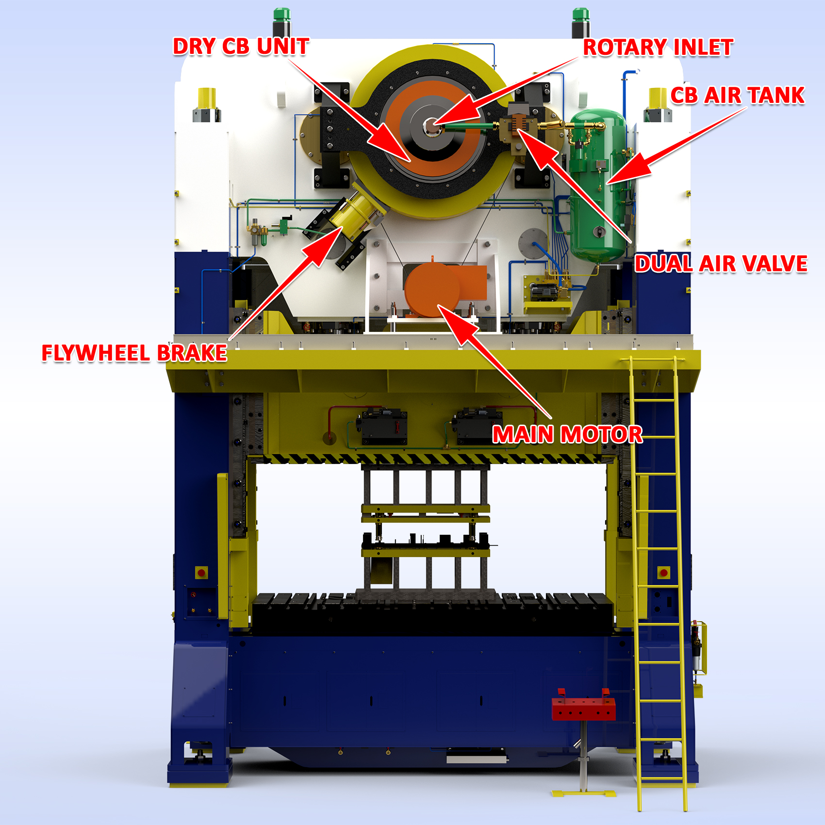
CB / Clutch Brake Systems
Fundamentals & Importance
Air Clutch & Brake Systems are a crucial part to mechanical presses. If any part of the air system to the CB System is leaking or not functioning properly, it should be reported to maintenance supervisor immediately.
All presses should be equipped with an CB pressure gage and regulator. This is to be set to the proper operating pressure and shown in your press or clutch & brake manual. Once set to proper pressure, this does not need and should not be adjusted as improper settings will cause damage to the CB lining plates. This is true for both dry and wet clutch presses.
Failure to make sure CB system is operating correctly and with the proper stroke travel of the lining plates will cause excessive wear.
√ Caution: Always inspect die area before activating CB dual run buttons, make sure no tools are left in die are and that no person is in die area and that proper point of operations guards are in place.
√ Maintenance should do weekly tests and inspections, Inch mode = stop and start are smooth, Single stroke mode = slide stop near TDC / Top Dead Center after each stroke, Continuous mode = slide stops immediately when e-stop is presses or slide stops near TDC when top stop is presses.
√ Slide should not overrun TDC, if this does happen causes could be, brake lining wear, or adjustment needed on dry CB unit or exhaust muffler on electronically monitor clutch valve may need cleaning.
√ Maintenance should drain CB air supply tank weekly to remove and moisture from system.
√ Understand the flow, CB air supply tank to filter to lubricator to air inlet rotary joint that feeds the air into clutch to engage and activate slide movement.
√ Flywheel brake, not to be confused with CB unit, is supplied to stop flywheel rotation once main motor is turned to the Off position. This allows operators or die set up team to enter the die area knowing that flywheel is not moving, and slide cannot be activated.
√ Maintenance should inspect flywheel brake travel, pad thickness and function on a monthly basis.
√ For presses with Wet CB units, it is Critical that oil level is correct, and that oil is clean. Failure to do so will cause excessive wear to CB lining plates which will eventually overheat and in some cases warp.
Click here for Air Flow Best Practices.
Click here for free Press Terminology document.
.
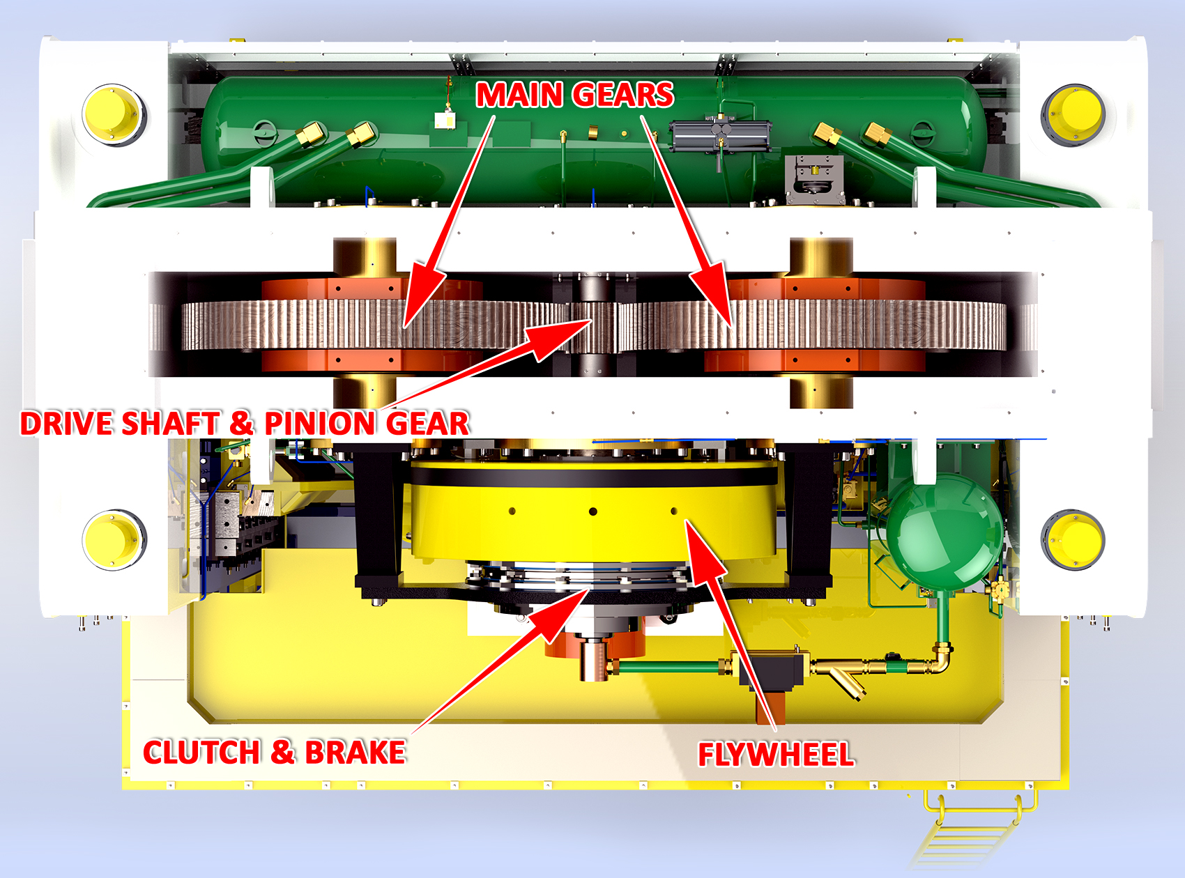
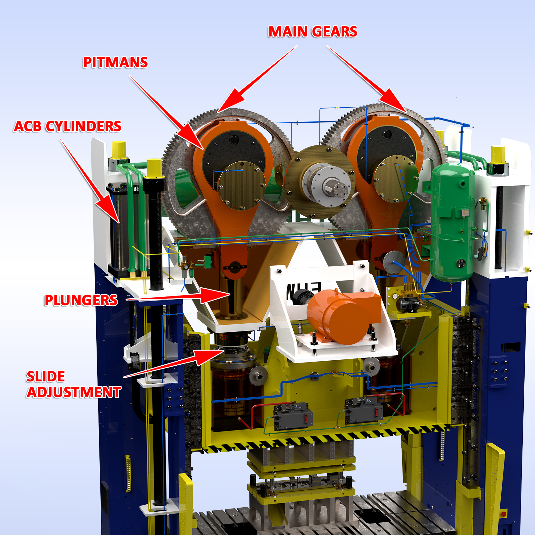
Connection Points & Drive Systems
Fundamentals & Importance
Think of the leg bone connected to the knee joint connected to the shin bone connected to the ankle bone.
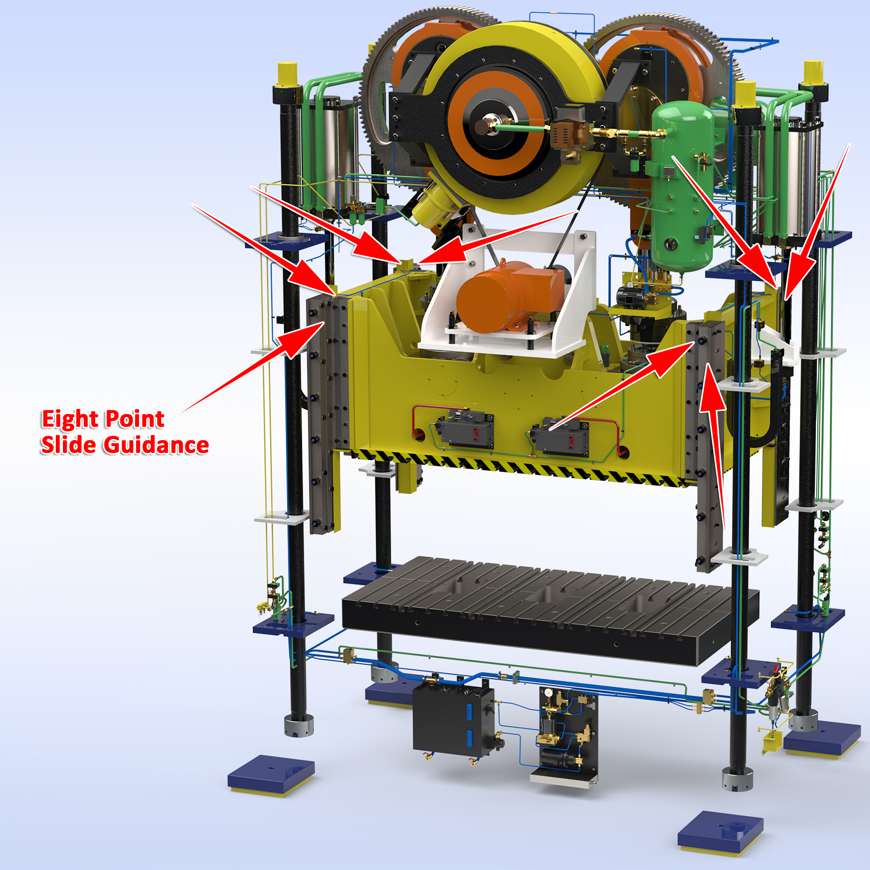
Now apply this to a mechanical press, the 1. clutch & brake are connected to the drive shaft & flywheel, pinion gear is 2. connected to the main gear’s connected to the 3. pitman’s or crankshafts connected to the 4. connecting rod connected to the 5. ball screw connected to the 6. suspension point ball seat which is connected to the 7. Slide which is guided by the 8. slide guidance gib system.
The press drive system is documented when new and total allowable / total stack up clearances which should be measured, documented during preventative maintenance every year and compared to as built.
√ All the 11 systems covered in this Maintenance Tips document have a purpose, cause and effect on the connection points in your press. Improper use of any of the 10 areas mentioned in this document will cause damage to drive train which expensive to repair.
√ Regular inspections and oil changes should be made and documented to assure press performance and to avoid any unnecessary wear to each connection point.
√ Maintenance can easily measure total stack up clearances. Remove and clean die area, exhaust all air pressure to ACB System so connection move down, install two dial indicator gauges between slide and bolster and then turn up air pressure on ACB System and document total movement and parallelism from left to right.
√ Caution: High Shock applications such as blanking, piercing create reverse snap thru tonnage which should not exceed more than 10% of total press capacity to avoid damaging drive components.
√ Click here to learn more about Reverse Tonnage.
√ It is recommended to change oil in all systems every year. Oil sample should be taken and sent out for analysis to detect any metal particles that may be present.
Click here for free Press Terminology document.
.
Control Systems / Electrical Panels
Fundamentals & Importance
Press control systems should be designed for the highest safety for operators of presses. No one should operate a press unless they have been fully training and read the press manual and this Maintenance Tip document.
Point of operation guards are the sole responsibility of the end user. All point of operation guards should be check at a minimum weekly. Every effort to prevent access to the pinch point area should be made.
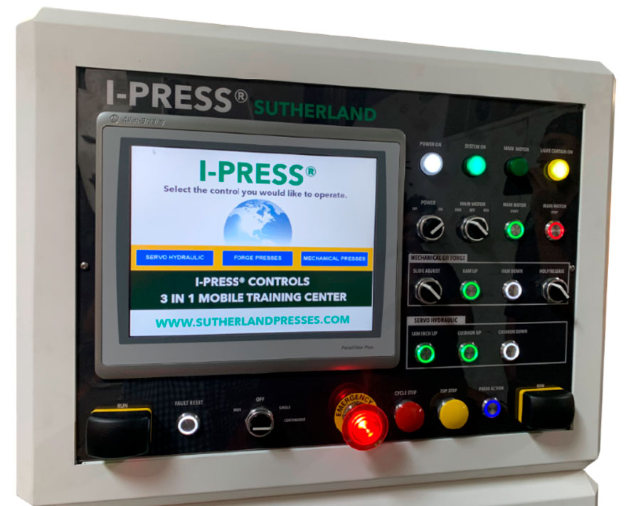
In this document we will refer the latest technology of I-PRESS & Automation controls which in most cases will have more features than presses with other or older controls.
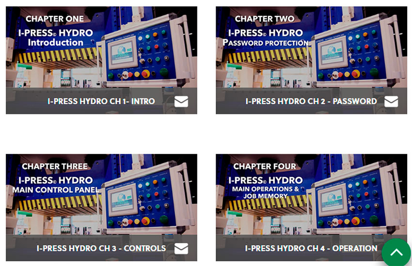
Click here for Mechanical I-PRESS tutorial.
Click here for Servo Hydraulic I-PRESS tutorial.
√ Never make modifications to press controls or wiring without approval.
√ Electrical panels should be clean, locked with main breaker disconnect switch.
√ Any changes or auxiliary equipment additions to be wired into the press control should be reviewed and approved with the press builder and refer to the original electrical schematics.
√ Any approved changes should be marked up on master electrical schematic with date and time in file name, so you know you are always looking at the current electrical schematic.
√ I-PRESS comes with 3 levels of passwords, Level 1 = operator, Level 2 = supervisor, Level 3 = Sutherland technician.
√ Press controls and functions should be checked weekly to make sure all systems are working.
√ Maintenance (at a minimum) to check all modes of operation and confirm proper operation, including: Off, Inch, Single and Continuous modes of operation, Emergency Stop, Top Stop, Hydraulic Overload, Slide Adjustment and confirm that it stops at the upper and lower factory set points. Also, to check and confirm that all Point of Operation Guards are in place and working properly.
*NOTE –
If in doubt about and control function or feature, stop what you are doing and ask your supervisor.
I-PRESS 4.0 Industry Standard meets the highest safety requirement, Performance Level D & Cat-3.
Click here for free Press Terminology document.
.
Gib, Slide Guides and Parallelism
Fundamentals & Importance
The up and down travel of the slide needs to be parallel, precise, accurate and repeatable to extend die life between die maintenance. Most straight side presses have 8-point guidance (see photo on next page) while smaller gap frame presses or OBI presses may have 6 point of 4 point respectively, but the principal is the same.
√ Check all gib surfaces to make sure they are getting lubrication from automatic oil re-circulating system or automatic grease pump depending on your press.
√ Check for scoring marks on replaceable bronze liners which indicate gibs are to tight or lack of lube.
√ Trace all lube lines and distributor blocks from lube source and confirm in good non leak condition.
√ For presses with automatic re-circulating oil be sure to check oil level at tank, clean filters and make sure that oil catch trays at the bottom of each gib are clean and free of any debris.
√ Adjusting the slide guides should only be done by experienced maintenance staff.
√ Slide must be confirmed to be parallel to bolster plate on all four corners. We suggest that you use a dial indicator and start at the right front and mark this as 0.0 start point, then go to left front, left rear and then right rear and mark the measurement as shown on the dial indicator and document your work.
√ Check the manufactures suggested clearance for each gib surface and set accordingly.
√ Once gibs are set, then be sure to do proper testing with press in continuous cycle mode, check that all surface is properly lubricated, and we strongly suggest using a heat gun to measure and document temperatures at the lower, middle and upper section of each gib.
Click here for free Press Terminology document.
.
HOLP / Hydraulic Overload Protection
Fundamentals & Importance
Most presses today come equipped with a HOLP (hydraulic overload protection) system that serves two purposes, to free stuck dies near BDC / Bottom Dead Center and to protect the press drive system. Most HOLP system are set to release pressure and stop the press when 110% of press capacity is reached.
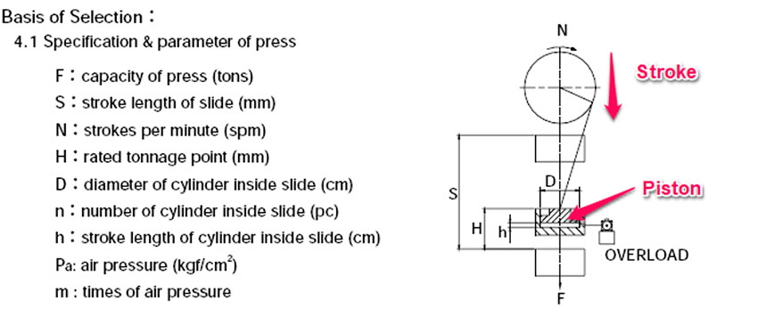
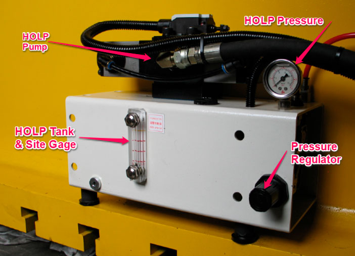
√ In most cases, HOLP systems are air over hydraulic systems which consist of a Keyed HOLP Release switch to solenoid mounted on the HOLP pump, a HOLP pump, pressure gage, regulator and hydraulic tank with site gage which feed a pressurized piston under each suspension point in the slide. See “h” on diagram on next page.
√ Never overfill the HOLP tank, when system is pressurized and press in ready to run condition, the oil level should be at the mid-point on the site gage. When the HOLP is activated in release pressure the oil under the suspension points in slide needs to evacuate which will raise the tank level closer to full.
√ Never change pressure setting from factory recommended setting. Changing this pressure setting will cause damage to the press.
√ It is suggested to operate the HOLP system once a week to confirm proper function. A good way to do this is to put a dial indicator between bolster and slide, turn-key to release position and measure the upward travel of the slide. Note: ACB Air Counter-Balance pressure may need to be turned up to overcome the slide and tooling weight.
Click here for free Press Terminology document.
.
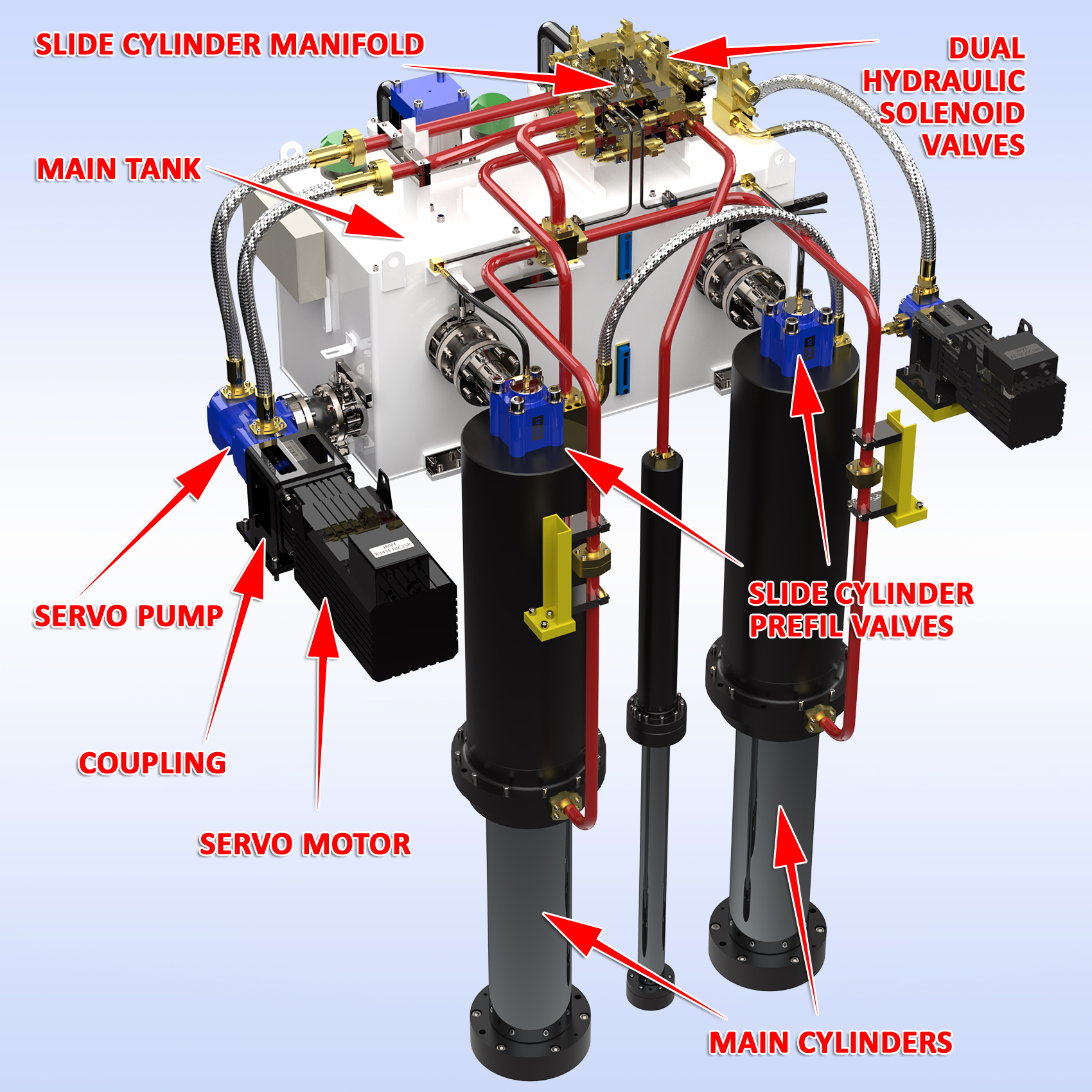
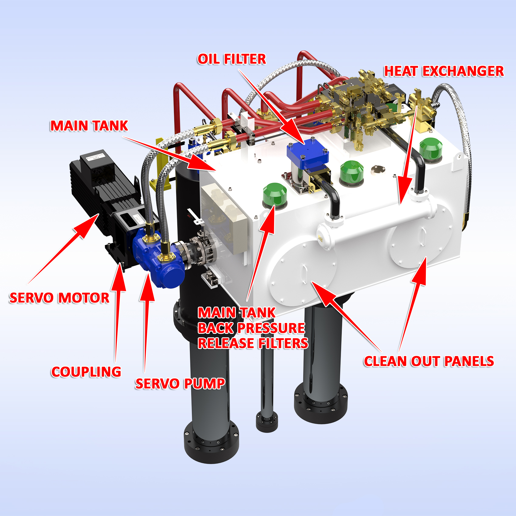
Hydraulic Fluid Management Systems
Fundamentals & Importance
This section applies to traditional hydraulic presses and our Servo Hydraulic Presses. It is critical that the oil in your press fluid management system is clean to prevent damage to valves, cylinders and all components that the oil encounters. Temperature control is also important to prevent breakdown of oil viscosity and lubricating properties.
√ Understand your Hydraulic system, schematic, flow direction, tank, heat exchanger, filters, manifolds, electronically monitored flow control valves, shut off valves, flange connection, cylinders, etc.
√ Check main tank level and top-off as needed.
√ Oil samples should be taken annually and sent out for analysis to check for any debris or metal breakdown that may be present.
√ Oil and Filter change and tank clean out should be done annually to extend component life.
√ Make sure heat exchanger mounted on tank is working properly and has good glow of cooling water from water tower or chiller. For presses with the I-PRESS Servo Hydro Control, oil temperature is shown on the main run screen.
√ Check all low- and high-pressure hoses and confirm no abrasions and that fittings are tight.
√ Never adjust any of the valves on the manifold, this should only be done by a certified maintenance technician. When replacing valves always set pressures to factory recommend settings.
√ Check all hold down bolts for everything, including motor, couplings and be sure they are secure.
Click here for free Press Terminology document
.
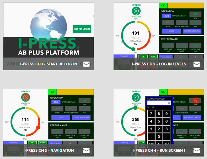
I-PRESS & Automation Controls
Fundamentals & Importance
Personnel safety is paramount for any presses no mater what type of controls it is equipped with. I-PRESS & Automation controls are the most advanced 4.0 control on the market. We have a family of controls for Servo Hydraulic, Mechanical Stamping and Forge Presses. To learn more visit: https://www.sutherlandpresses.com/i-press
√ Fully featured press and automation controller with large color touch screen interface.
√ Available on Rockwell AB, Siemens and Omron hardware and software platforms.
√ Can be connected to mobile devices or network to extract crucial production data and operator assistance from approved remote devices.
√ Easy navigation screens are so intuitive your team can learn the control in a matter of hours.
√ Open architecture is expandable for ease of additions or customization as needed.
√ Performance monitoring with fault diagnostics with the push of a button.
√ Job memory library stores job info for quick set up when job is to be run again.
√ Namable programable cams x 12 sets (expandable)
√ Namable die protection x 16 (expandable)
√ Electronic tonnage monitor with settable high and low limits saved for each job.
√ Over 110 machine monitoring system with fault display at the top of main run screen.
Click here for free Press Terminology document.

.
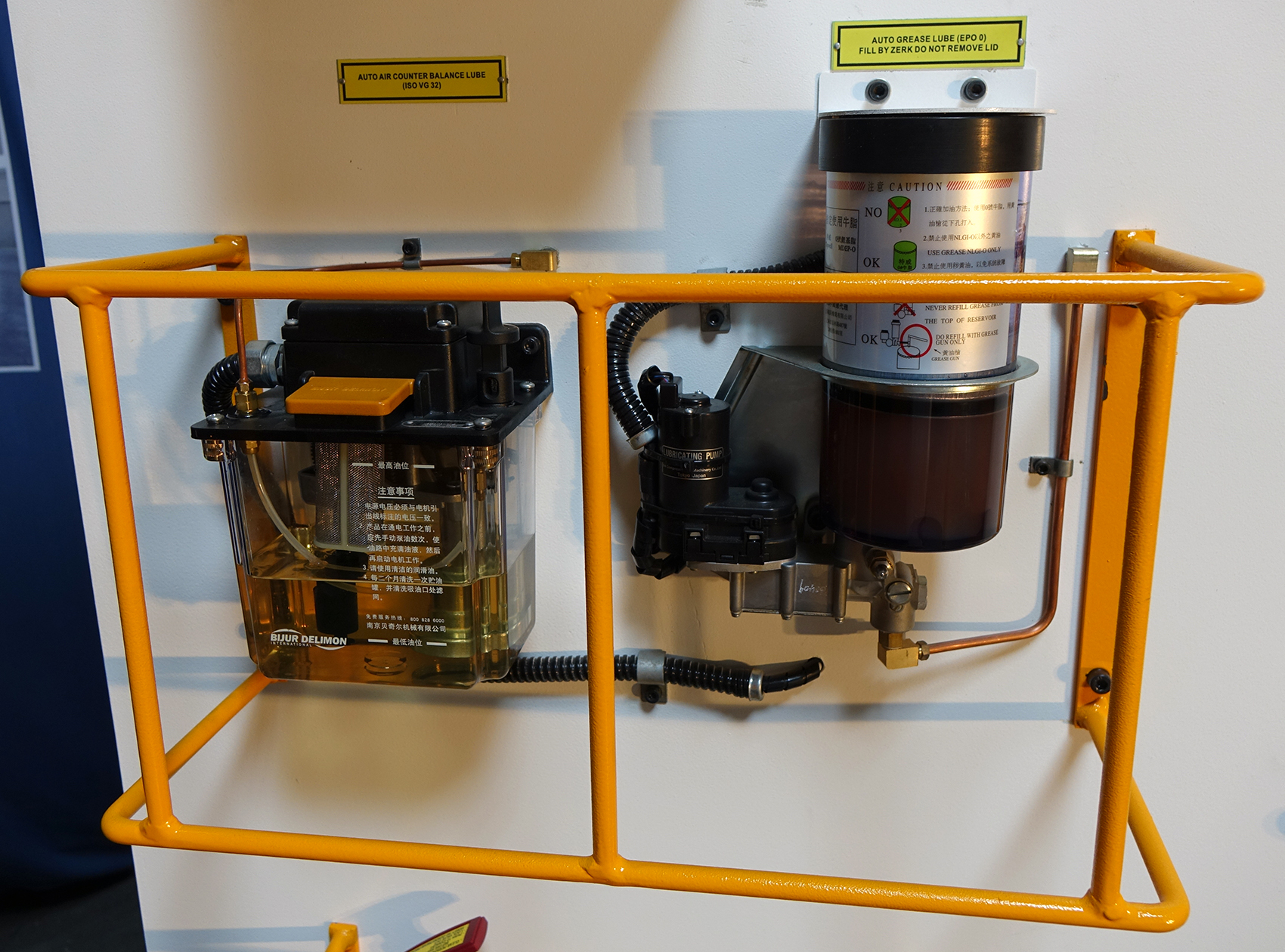
Lubrication Systems
Fundamentals & Importance
No matter what type of press and lubrication systems are a crucial part of keeping your press running smoothly and preventing major damage. Heat build up and the drive system and slide guidance can cause expensive downtime and repairs.
√ GREASE LUBE: Smaller presses may be equipped with a grease lubrication system. In most cases, this is made up with a grease reservoir and pump, lube lines to distributor block and hard or flexible connections to the various points of lubrication.
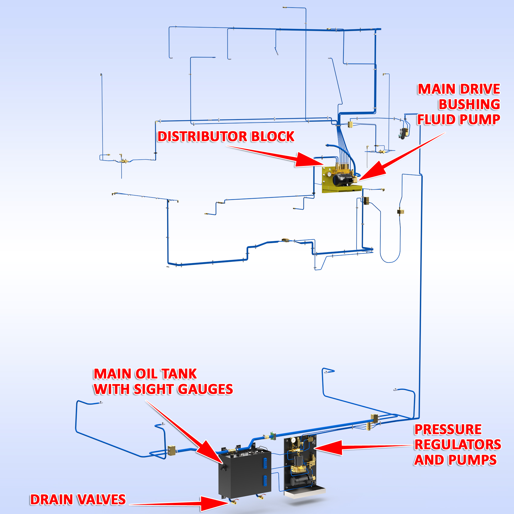
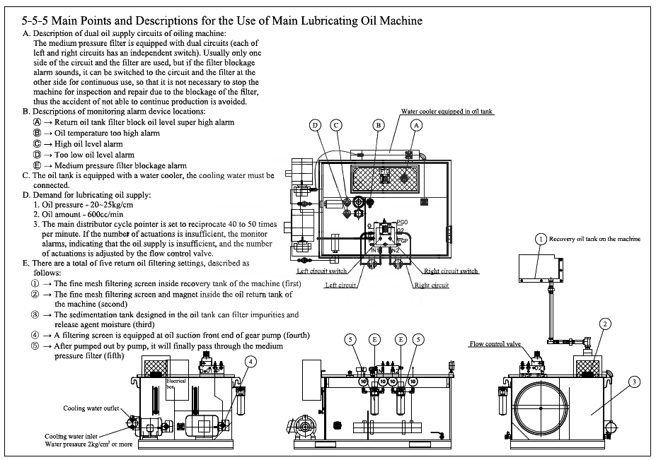
√ AUTOMATIC OIL LUBE: Larger presses are normally equipped with automatic re-circulating oil systems. This is made up with main oil tank, site gage, oil return lines, filters, pump, pressure regulator, multiple distribution blocks with electronic flow detectors and hard or flexible connections to the various points of lubrication.
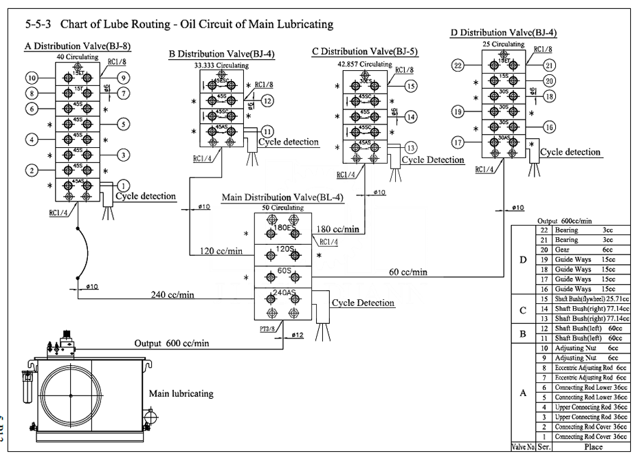
√ Always refer to the lubrication schematic so you know and understand the importance of each point to be lubricated.
√ A daily inspection should be made of lube system and lube final delivery points to assure good grease or oil flow to surface.
√ Proper lubricants as specified by the press manufacture should only be used. Do Not mix different lubricant types and it can cause contamination and blockage.
Click here for free Press Terminology document.
.
PMP / Preventative Maintenance Programs
Fundamentals & Importance
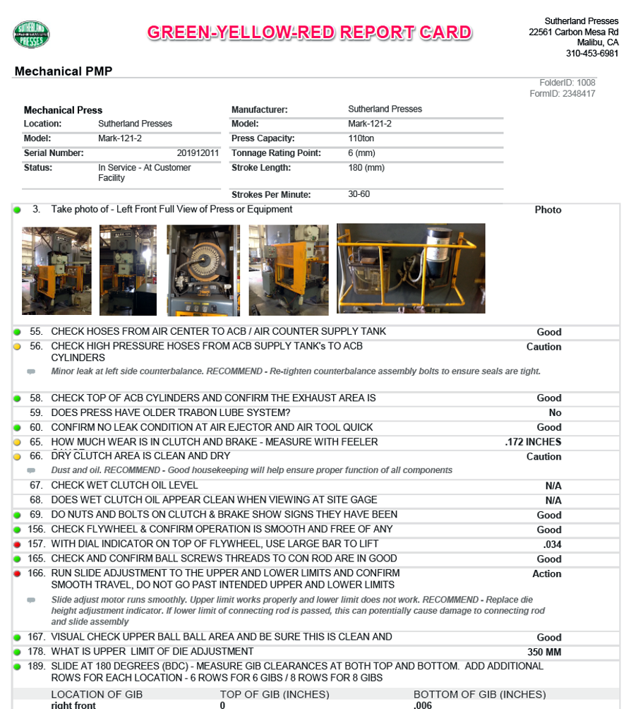
Our PMP programs prove to increase press up-time and reduce maintenance. We document all press systems with photos and detailed description of status. A grade of Green-Yellow-Red indicator makes it easy for the end user and management team know where key issues are that need to be addressed. (See sample on next page).
Obviously capital equipment is expensive and the return on investment is very important. The systems and fundamentals mention in the 11 step Maintenance Tip for presses need to be ingrained into operators, set up and maintenance teams.
At Sutherland Presses and 3 generations in the business, we have seen about every type of problem that can be imagined. As the footer of this document states, “A good description of the problem is half the solution”.
A great way to think of your press is by system, cause and effect and related components in the chain. This allows companies to diagnose, identify and solved press equipment problems.
If you would like a quote for PMP on your presses, e-mail: service@sutherlandpresses.com
Click here for free Press Terminology document.
______

To get the most lifetime value out of your machines, a comprehensive maintenance plan is an absolute must to avoid press repair. Our Preventative Maintenance Plans are the best way to ensure your presses stay in top shape for years of efficient operation.
We highly recommend a PMP every 6 months if you are running multi shifts, or annually for a single shift.
For additional peace of mind, we recommend establishing sets of daily, weekly, monthly, 6 month, and 12 month internal maintenance checks for each of your mechanical presses, hydraulic presses and forge presses.
To help you keep track of your internal press maintenance, we’ve created a set of log sheets available as PDF downloads below:


