Ease of use and connectivity to external devices, industry 4.0
SAFETY - CONNECTIVITY - FLEXIBILITY
Sutherland is proud to introduce I-PRESS®, the future of press control technology. With software based controls and touchscreen displays, I-PRESS® represents our commitment to leading the industry with the latest in controls innovation. The metal forming industry is evolving to a new level of connectivity and automation, and I-PRESS® has been designed to bring your press operations into the 21st century.
- The world’s most intuitive press control
- Full suite of safety features
- Built for automation and expandability
- Designed to integrate seamlessly with Connected Enterprise

I-PRESS® is built for customization and expandability. When new features or modifications are needed, there are no costly chip replacements, just unlock your upgrades directly from the software.
• Full suite of automation tools
• Easy integration with feeders, robots, and transfer systems
• Customizable to support special applications
Main Run Screen Mechanical
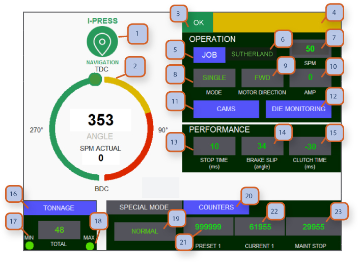
1. NAVIGATION BUTTON: Pressing this takes you to navigation screens. Depending on password level for operator or supervisor, more or less screens are accessible.
2. STROKE POSITION & ANGLE INDICATOR & ACTUAL SPEED: This angle should be the same as mechanical clock type indicator on Press crown. Angle is shown based on the electronic encoder which monitors slide position & overrun position. Encoder Position can be re-calibrated, see “re-zero encoder”. Actual speed shows current SPM / strokes per minute.
3. OK MONITOR: Green display shows that all systems are functioning and no faults are present.
4. FAULT MONITOR: When any safety or machine fault is present, the fault will display in yellow and OK monitor will no longer be Green. Fault needs to be resolved and “reset button” at t-stand needs to be pressed to clear fault.
5. JOB BUTTON: Press this to go to “job memory” screen. This is where a new job can be loaded. From this location you can also Go to “job library” screen to pull up jobs that have been saved.
6. JOB NUMBER: 10 digit alpha-numeric job names can be assigned on “job memory” set up screen.
7. SPM: Displays current SPM/ strokes per minute speed setting of main motor, flywheel and slide motion. This is adjusted up/down by tapping field and entering a desired strokes per minute value.
8. MODE: field displays 5 different modes of operation, “off, inch, single stroke, continuous, special” modes. To start main motor, mode selector switch located in t-stand must be in the “off” position. “special mode” can only be accessed with Supervisor level password.
9. MAIN MOTOR DIRECTION: Displays 3 positions of motor direction key selector at mos / master operation station: “forward, flywheel brake, reverse”
Note: press will only operate in “inch mode” when in reverse. When middle position / flywheel brake is selected this will activate brake, stop slide movement, turn off main motor and apply flywheel brake.
10. AMP: displays main motor amp draw. This can be helpful when setting acb / air counter balance air pressure which equalizes upper die weight. Minimal fluctuation of amps indicate proper setting of acb pressure. If amps go up during 180 to 359 upstroke this indicates acb pressure may be to low. If amps go up during 0 to 180 down stroke indicates acb pressure may be too high.
11. CAM BUTTON: Press to go to programmable cam screen. Cams 1-12 are pre-wired on terminal strips in lower section of mep / main electrical panel.
12. DIE PROTECTION: Press to go to “die protection” screen. Die pro 1-16 are pre-wired on terminal strips in lower section of mep / main electrical panel.
13. STOP TIME: Displays stopping time in ms / milliseconds every stroke. Parameter settings are accessible with supervisor password.
14. BRAKE SLIP: Displays slip angle. Parameter settings are accessible with supervisor password.
15. CLUTCH TIME Displays clutch engagement time in ms / milliseconds. Parameter settings are accessible with supervisor password.
16. TONNAGE: Press to go to tonnage screen, field below shows total tonnage during each stroke of the press.
17. MIN TONNAGE: Displays red indicator if min tonnage setting on job memory screen goes below a preset limit. Slide will stop at tdc / top dead center and hmi will display “min tonnage” fault at upper right on main run screen. Press “reset button” at t-stand to clear fault.
18. MAX TONNAGE: Displays red indicator if max tonnage setting on job memory screen goes above a preset limit. Slide will stop at tdc / top dead center and hmi will display “max tonnage” fault at upper right on main run screen. Press “reset button” at t-stand to clear fault.
19. SPECIAL MODE OF OPERATIONS: Optional, accessible with supervisor password. This allows 4 settings, “normal operations mode-micro inch, ssd / single stroke on demand, csd / continuous stroke on demand” this is ideal for presses that are slaved to upstream or downstream automation.
20. COUNTERS: Press to go to counters screen where you can adjust the counter values.
21. PRESET COUNTER 1: Displays preset 1 counter on counter screen. This can be used as a batch counter.
22. CURRENT COUNT 1: Displays the current count from when counter was started. When this reaches same number as preset 1, slide will stop at tdc and green OK monitor will go off and will display “preset 1 count” fault at upper right on main run screen. Go to counter screen to re-zero or set new value.
23. MAINTENANCE STOP: Displays countdown to maintenance stop. Green OK monitor will go off and will display “maintenance count” fault at upper right on main run screen. Supervisor password is required to clear or reset maintenance counter. Then press “reset button” at t-stand to clear fault.
Note: When counters (#21 & #22 & #23) reaches 80% of its preset value, it will turn yellow. When it reaches 90% of its preset value it will turn red. This is so that the operator can be prepared for the press to stop.
• Option 1: BAR-CODE SCANNER: Press to use the bar-code scanner and automatically load a preset job linked to that bar-code.
• Option 2: STROKE SEQUENCE COUNTER: Displays customizable stroke counter.
• Option 3: QDC: Press to go to quick die change screen in order to operate die clamps and die lifters.
• Option 4: AUTO DIE HEIGHT: Displays die height in mm or inches. Can be programmed in job memory to eliminate operators use of the manual die height adjustment.
• Option 5: CONTINUOUS RUN TIME: Displays how long the press has been running in continuous mode.
Main Run Screen Servo Hydraulic
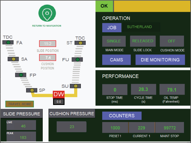
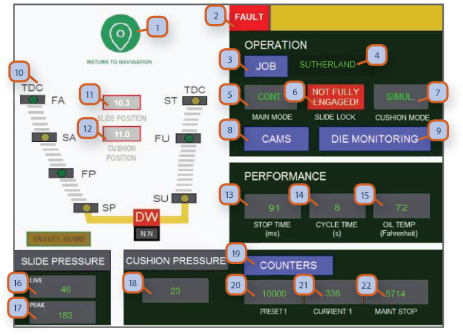
1. NAVIGATION BUTTON: Pressing this takes you to navigation screens. Depending on password level for operator or supervisor, more or less screens are accessible.
2. OK MONITOR: Green "OK" display shows that all systems are functioning and no faults are present. Red 'fault' displays indicates there is a fault present and the press will not operate.
3. JOB BUTTON: Press this to go to “job memory” screen. This is where a new job can be loaded. From this location you can also go to “job library” screen to pull up jobs that have been saved.
4. JOB NUMBER: 10 digit alpha-numeric job names can be assigned on “job memory” set up screen.
5. MODE: Field displays 5 different modes of operation, “off, inch, single stroke, continuous, special” modes. To start main motor, mode selector switch located in t-stand must be in the “off” position. “special mode” can only be accessed with supervisor level password.
6. SLIDE LOCK-'NOT FULLY ENGAGED': Shows this fault when the slide locks are not fully engaged. When slide locks are retracted all the way, this field will show "Released" in green. See next page.
7. CUSHION MODE: Toggle between off, simultaneously or delay. In simultaneously mode, the cushion will rise as soon as the ram start rising after reaching bdc. In delay mode, the cushion will rise with a set amount of delay time, after ram start rising from bdc.
8. CAM BUTTON: Press to go to programmable cam screen. Cams 1-12 are prewired on terminal strips in lower section of mep / main electrical panel.
9. DIE MONITORING: Press to go to “die monitoring” screen. Die pro 1-16 are prewired on terminal strips in lower section of mep / main electrical panel.
10. STROKE POSITION & STROKE STAGE INDICATOR: Position of slide shown is based on the linear transducer which monitors slide position.
11. SLIDE POSITION: Displays current slide position in mm.
12. CUSHION POSITION: Displays current cushion position in mm.
13. STOP TIME: Displays stopping time in ms / milliseconds every stroke. Parameter settings are accessible with supervisor password.
14. CYCLE TIME: Displays the total cycle time in seconds.
15. OIL TEMP: Displays oil temp in Fahrenheit .
16. SLIDE PRESSURE - LIVE: This field displays current slide pressure (tonnage) at any given moment.
17. SLIDE PRESSURE - PEAK: This field displays the highest pressure value from the last stroke.
18. CUSHION PRESSURE: Displays cushion pressure.
19. COUNTERS: Press to go to counters screen where you can adjust the counter values
20. PRESET COUNTER 1: Displays preset 1 counter on counter screen. This can be used as a batch counter.
21. CURRENT COUNT 1: Displays the current count from when counter was started. When this reaches same number as preset 1, slide will stop at tdc and green OK monitor will go off and will display “preset 1 count” fault at upper right on main run screen. Go to counter screen to re-zero or set new value.
22. MAINTENANCE STOP: Displays countdown to maintenance stop. Green OK monitor will go off and will display “maintenance count” fault at upper right on main run screen. Supervisor password is required to clear or reset maintenance counter.
Main Run Screen Forge
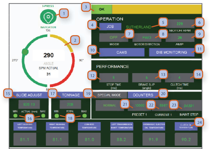
1. NAVIGATION BUTTON: Pressing this takes you to navigation screens. Depending on password level for operator or supervisor, more or less screens are accessible.
2. STROKE POSITION & ANGLE INDICATOR & ACTUAL SPEED: This angle should be the same as mechanical clock type indicator on press crown. Angle is shown based on the electronic encoder which monitors slide position & overrun position. Encoder position can be re-calibrated, see “re-zero encoder”. Actual speed shows current SPM / strokes per minute.
3. OK MONITOR: Green display shows that all systems are functioning and no faults are present. When any safety or machine fault is present, the fault will display in the yellow area and ok monitor will no longer be green. Fault needs to be resolved and “reset button” at t-stand needs to be pressed to clear fault.
4. JOB BUTTON: Press this to go to “job memory” screen. This is where a new job can be loaded. From this location you can also go to “job library” screen to pull up jobs that have been saved.
5. JOB NUMBER: 10 digit alpha-numeric job names can be assigned on “job memory” set up screen.
6. MOTOR RPM: Displays current motor rpm / rotations per minute speed setting of main motor.
7. MODE: Field displays 5 different modes of operation, “off, inch, single stroke, continuous, special” modes. To start main motor, mode selector switch located in t-stand must be in the “off” position. “special mode” can only be accessed with supervisor level password.
8. MAIN MOTOR DIRECTION: Displays 3 positions of motor direction key selector at mos / master operation station: “forward, flywheel brake, reverse” note: press will only operate in “inch mode” when in reverse. When middle position / flywheel brake is selected this will activate brake, stop slide movement, turn off main motor and apply flywheel brake.
9. AMP: Displays main motor amp draw. This can be helpful when setting acb / air counter balance air pressure which equalizes upper die weight. Minimal fluctuation of amps indicate proper setting of acb pressure. If amps go up during 180 to 359 upstroke this indicates acb pressure may be to low. If amps go up during 0 to 180 down stroke indicates acb pressure may be too high.
10. CAMS BUTTON: Press to go to programmable cam screen. Cams 1-12 are pre-wired on terminal strips in lower section of mep / main electrical panel.
11. DIE MONITORING: Press to go to “die protection” screen. Die pro 1-16 are pre-wired on terminal strips in lower section of mep / main electrical panel.
12. STOP TIME: Displays stopping time in ms / milliseconds every stroke. Parameter settings are accessible with supervisor password.
13. BRAKE SLIP: Displays slip angle. Parameter settings are accessible with supervisor password.
14. CLUTCH TIME: Displays clutch engagement time in ms / milliseconds. Parameter settings are accessible with supervisor password.
15. SLIDE ADJUST: Displays current die height.
16. MIN/MAX INDICATORS: Will display a red indicator if the die height reaches the physical min die height limit.
17. TONNAGE: Press to go to tonnage screen, field below shows total tonnage during each stroke of the press.
18. MIN/MAX INDICATORS: Displays red indicator if min tonnage setting on job memory screen goes below a preset limit. Slide will stop at tdc / top dead center and hmi will display “min tonnage” fault at upper right on main run screen. Press “reset button” at t-stand to clear fault.
19. SPECIAL MODE OF OPERATIONS: Optional, accessible with supervisor password. This allows 4 settings, “normal operations mode-micro inch, ssd / single stroke on demand, csd / continuous stroke on demand” this is ideal for presses that are slaved to upstream or downstream automation.
20. COUNTERS: Press to go to counters screen where you can adjust the counter values
21. PRESET COUNTER 1: Displays preset 1 counter on counter screen. This can be used as a batch counter.
22. CURRENT COUNT 1: Displays the current count from when counter was started. When this reaches same number as preset 1, slide will stop at tdc and green ok monitor will go off and will display “preset 1 count” fault at upper right on main run screen. Go to counter screen to re-zero or set new value.
23. MAINTENANCE STOP: Displays countdown to maintenance stop. Green ok monitor will go off and will display “maintenance count” fault at upper right on main run screen. Supervisor password is required to clear or reset maintenance counter. Then press “reset button” at t-stand to clear fault.
24. VARIOUS TEMP INDICATORS: This area allows you to monitor the temperature in different areas of the press. These fields will turn red if the temp rises over a set limit.
Note:
When counters (#21 & #22 & #23) reaches 80% of its preset value, it will turn yellow. When it reaches 90% of its preset value it will turn red. This is so that the operator can be prepared for the press to stop.
Color Touch Screen Navigation
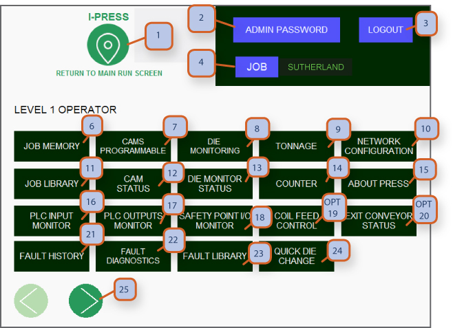
1. NAVIGATION BUTTON: Pressing this takes you to navigation screens. Depending on password level for operator or supervisor, more or less screens are accessible.
2. ADMIN PASSWORD: Press to allow supervisor or higher password to be entered. Return to lower level password, use logout button.
3. LOGOUT: This allows users to logout so others can login with their password level.
4. JOB: Press to go to “job memory” screen.
5. JOB NUMBER: Displays current 10 digit alphanumeric job that is selected.
6. JOB MEMORY: Press to go to “job memory” screen.
7. CAMS PROGRAMMABLE: Press to go to “programmable cams” screen.
8. DIE MONITORING: Press to go to “die monitoring” screen.
9. TONNAGE: Press to go to “tonnage monitor” screen.
10. NETWORK CONFIGURATION: Shows plc type and safety I/o modules.
11. JOB LIBRARY: Press to go to “job library screen” to select a pre-programmed job or enter a new job.
12. CAM STATUS: Press to go to cam status screen. (view only)
13. DIE MONITORING STATUS: Press to go to die monitoring screen. (view only)
14. COUNTER: Press to go to “counter screen” “preset 1, preset 2, cut counter 1, cut counter 2, maintenance & total life counter”.
15. ABOUT PRESS: Press to see press specifications & I-press control manual.
16. PLC INPUT MONITOR: Press to go to “plc-1 inputs monitor” screen, great for trouble shooting.
17. PLC OUTPUT MONITOR: Press to go to “plc-1 outputs monitor” screen, great for trouble shooting.
18. SAFETY POINT I/O MONITOR: Press to view I/O status of the plc.
19. **optional** COIL FEED CONTROL: Coil feed control through I-press hmi.
20. **optional** EXIT CONVEYOR STATUS: Exit conveyor control through I-press hmi.
21. FAULT HISTORY: Press to go to “fault history” screen.
22. FAULT DIAGNOSTICS: Press to go to “fault diagnostics” screen.
23. FAULT LIBRARY: Press to go to fault library.
24. QUICK DIE CHANGE: Press to go to QDC screen where you can control your die clamps / lifter.
25. SCROLL RIGHT: Press to go to level 2 operator screen.
Cams Programmable & Nameable Mechanical & Forge
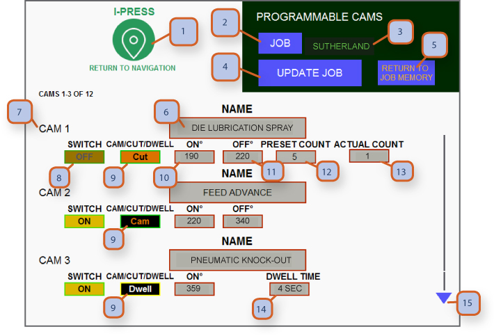
1. NAVIGATION BUTTON: Pressing this takes you to navigation screens. Depending on password level for operator or supervisor, more or less screens are accessible.
2. JOB: Press to go to “job memory” screen. You have arrived.
3. JOB NUMBER: Displays current 10 digit alphanumeric job that is selected.
4. UPDATE JOB: After you have set the cams best suited for the job, press save update job button and then return to job memory Screen.
5. RETURN TO JOB MEMORY: Press blue hot key to return to job memory screen. Once there you can then go on to die monitoring, tonnage & counter screens to complete your job set up and save the job. (follow instructions on job memory screen on the steps for setting up a new job)
6. CAM NAME: Cam 1 is fixed to air ejector system, cams 2-12 can be named as needed when you wire in your automation or feed lines.
7. CAM NUMBER: Displays the cam number.
8. SWITCH: Is a toggle button to turn cams on/off.
9. CAM/CUT/DWELL: Any cam can be selected to be either cam, cut or dwell. In cam mode, you can select the on and off angles for the cam to fire during each stroke. In cut mode, you can set the on and off angles for the cam to fire as well as a stroke interval with a preset value. In dwell mode, you can set a delay time for the cam to fire.
10. ON ANGLE: Press here to enter the angle for the device / signal to come on.
11. OFF ANGLE: Press here to enter the angle for the the device / signal to come off.
12. PRESET COUNT: Press here to set the number of strokes interval for the cam to fire.
13. ACTUAL COUNT: This number will increase with each stroke until reaching the preset value (preset count - #12). Once the preset value has reached, the selected cam will turn on and the actual count display will reset back to 0.
14. DWELL TIME: When cam is set to dwell mode (#9 = dwell) press here to set the delay time in seconds for this cam to turn on. Cam will only activate after dwell time count down is complete. Should only be used in single stroke mode.
Note:
• If you need more cams, use the scroll arrow to access cam 4-12.
• Now that you have set up your cams, press save job to return to job memory screen.
• Your mep / main electrical panel has been pre-wired with terminal blocks with 5 amp relays to tie in your automation. In most cases these are in the lower section of your mep, located next to other field accessible terminal blocks for die monitoring, e-stop, cycle stop & top stop.
Cams Programmable & Nameable Servo Hydraulic
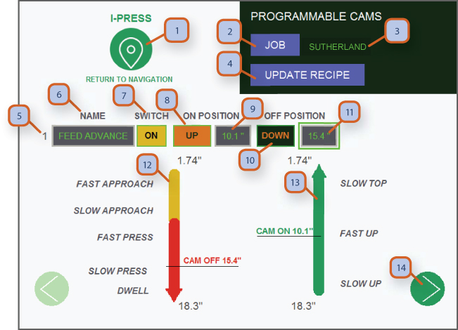
1. NAVIGATION BUTTON: Pressing this takes you to navigation screens. Depending on password level for operator or supervisor, More or less screens are accessible.
2. JOB: Press to go to “job memory” screen. You have arrived.
3. JOB NUMBER: Displays current 10 digit alphanumeric job that is selected.
4. UPDATE RECIPE: After you have set the cams best suited for the job, press update recipe button and then return to job memory Screen.
5. CAM NUMBER: Displays cam's circuit number.
6. CAM NAME: Displays the current cam name.
7. SWITCH: Is a toggle button to turn cams on/off.
8. UP/DOWN ON POSITION: Toggle between up or down to change the part of the stroke in which the cam will turn on.
9. ON POSITION: Position for the cam to turn on in inches from tdc.
10. UP/DOWN OFF POSITION: You can enter the position that you want the device / signal to come on.
11. OFF POSITION: Position for the cam to turn off in inches from tdc (total length of stroke up to this point).
12. DOWN PART OF THE STROKE: This yellow-red line represents the 'down' part of the stroke. Adjust cam on/off position by sliding Your finger to the desired position.
13. UP PART OF THE STROKE: This green line represents the 'up' part of the stroke. Adjust cam on/off position by sliding your finger. To the desired position.
14. SCROLL: Press to scroll to next cam
Die Monitors Programmable & Nameable Mechanical & Forge
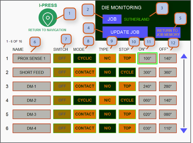
1. NAVIGATION BUTTON: Pressing this takes you to navigation screens. Depending on password level for operator or supervisor, more or less screens are accessible.
2. JOB: Press to go to “job memory” screen. You have arrived.
3. JOB NUMBER: Displays current 10 digit alphanumeric job that is selected.
4. UPDATE JOB: After you have set the dm 1 to 16 best suited for the job, and then press return to job memory screen.
5. RETURN TO JOB MEMORY: Press blue hot key to return to job memory screen. Once there you can then go on to cams, tonnage & counter screen to complete your job set up and save it. (Follow instructions on job memory screen on the steps for setting up a new job)
6. DIE MONITORING CIRCUIT NAME: Die monitors 1 to 16 can be named as needed when you wire in die monitor sensors.
7. SWITCH: Is a toggle button to turn die monitors on/off.
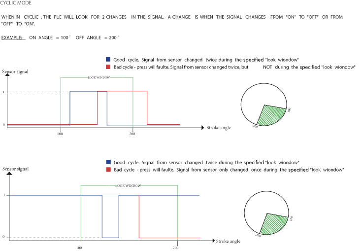
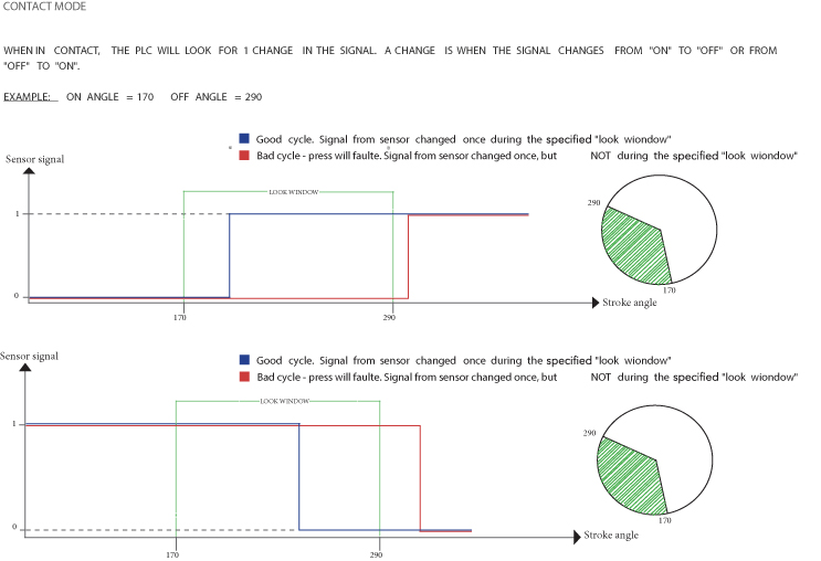
8. MODE: Allows you to toggle between contact or cyclic depending on the type of sensor in use. When in cyclic mode, the sensor will look for two state changes (from on to off and then off to on) during the stroke part specified by the on/off angles. If two state changes are not detected, the press will fault. When in contact mode, the sensor will look for one state change during the stroke part specified by the on/off angles. If no state change or more than one state change is detected, the press will fault. See pages 27-28 for more detailed explanation.
9. TYPE: Allows you to toggle between n/c normally closed or n/o normally open circuits depending on the type of sensor in use.
10. STOP: Allows you to toggle between top stop and cycle stop. Cycle stop is like e-stop but leaves all motors in running condition.
11. ON ANGLE: You can enter the angle that you want the device / signal to turn on.
Note:
• Now that you have set up your die monitoring, press save job return to job memory screen.
• Your mep / main electrical panel has been pre-wired with 16 terminal blocks for die monitoring. In most cases these are in the lower section of your mep, located next to other field accessible terminal blocks for programmable cams, e-stop, cycle stop & top stop.
Die Monitors Programmable & Nameable Servo Hydraulic
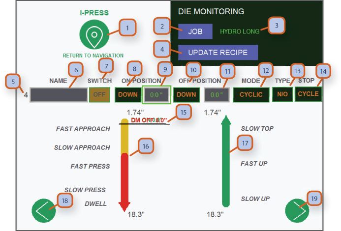
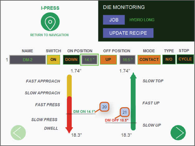
1. NAVIGATION BUTTON: Pressing this takes you to navigation screens. Depending on password level for operator or supervisor, More or less screens are accessible.
2. JOB: Press to go to “job memory” screen. You have arrived.
3. JOB NUMBER: Displays current 10 digit alphanumeric job that is selected. -
4. UPDATE RECIPE: After you have set the dm 1 to 16 best suited for the job, and then press return to job memory screen.
5. DIE MONITORING CIRCUIT NUMBER: Displays the number of currently displayed die protection / monitoring circuit.
6. NAME: Die monitors 1 to 16 can be named as needed when you wire in die monitor sensors.
7. SWITCH: Is a toggle button to turn die monitors on/off
8. DOWN/UP ON POSITION: Toggle between up or down to change the part of the stroke in which the die pro. Will turn on.
9. ON POSITION: Position for the die pro. To turn on in inches from tdc.
10. DOWN/UP ON POSITION: Toggle between up or down to change the part of the stroke in which the die pro. Will turn off.
11. OFF POSITION: position for the die pro. To turn on in inches from tdc (total length of stroke up to this point).
12. MODE: allows you to toggle between contact or cyclic depending on the type of sensor in use.
13. TYPE: Allows you to toggle between n/c (normally closed) or n/o (normally open) circuits depending on the type of sensor In use.
14. STOP: Allows you to toggle between top stop and cycle stop. Cycle stop is like e-stop but leaves all motors in running Condition.
15. ON/OFF POSITION SLIDERS: This is where both the on and off position sliders will appear when programming a new die pro. circuit. Slide each one to the desired location. See screen 8.2 #20 & #21 for another view.
16. DOWN PART OF THE STROKE: This yellow-red line represents the 'down' part of the stroke. Adjust cam on/off position by sliding your finger to the desired position.
17. UP PART OF THE STROKE: This green line represents the 'up' part of the stroke. Adjust cam on/off position by sliding your finger to the desired position.
18. SCROLL LEFT: Scroll left.
19. SCROLL RIGHT: Scroll right.
Note:
• Now that you have set up your die monitoring, press update recipe to return to job memory screen.
• Your mep / main electrical panel has been pre-wired with 16 terminal blocks for die monitoring. In most cases these are in the lower section of your mep, located next to other field accessible terminal blocks for programmable cams, e-stop, cycle stop & top stop.
Tonnage Monitor Mechanical
1. NAVIGATION BUTTON: Pressing this takes you to navigation screens. Depending on password level for operator or supervisor, more or less screens are accessible.
2. JOB: Press to go to “job memory” screen.
3. JOB NUMBER: Displays current 10 digit alphanumeric job that is selected.
4. UPDATE JOB: After you have set the high & low tonnage alarms best suited for the job, press job button.
5. RETURN TO JOB MEMORY: Press blue hot key to return to job memory screen. Once there you can then go on to cams, die monitors & counter screen to complete your job set up and make final save. (follow instructions on job memory screen on the steps for setting up a new job)
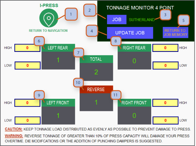
6. LEFT REAR: Displays tonnage load from left rear frame mounted strain link.
7. TOTAL: Displays total forward tonnage of each stroke.
8. RIGHT REAR: Displays tonnage load from right rear frame mounted strain link.
9. LEFT FRONT: Displays tonnage load from left front frame mounted strain link.
10. REVERSE: Displays reverse snap-through tonnage. (we recommend not exceeding more that 10% press capacity in reverse tonnage)
CAUTION: Keep tonnage load distributed as evenly as possible to prevent damage to press.
WARNING: Reverse tonnage of greater than 10% of press capacity will damage your press over time. Die modifications or the addition of punching dampers are recommended.
Note:
• Description applies for both 2-point and 4-point tonnage monitors.
• High & low tonnage limits can be customized for each job in the tonnage screen accessible from the main run screen or the operator level 1 navigation screen. If tonnage goes below or above the high & low levels, press will stop and fault will show on main run screen.
• Level your load. Off center loads are best to be avoided as this can cause uneven wear to your press slide guidance and drive components.
Tonnage Monitor / Pressure Setting Servo Hydraulic
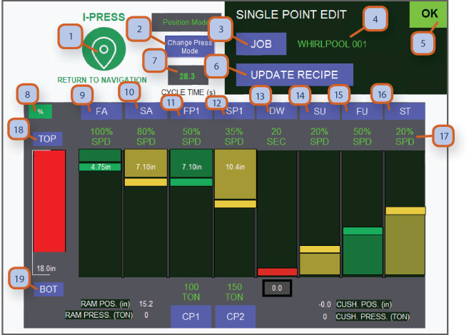
1. NAVIGATION BUTTON: Pressing this takes you to navigation screens. Depending on password level for operator or supervisor, more or less screens are accessible.
2. CHANGE PRESS MODE: Toggle between pressure and position. Pressure mode will make sure your pressure will reach the desired value, and position mode will make sure your position marker is reached regardless of the tonnage.
3. JOB: Press to go to “job memory” screen. You have arrived.
4. JOB NUMBER: Displays current 10 digit alphanumeric job that is selected.
5. OK MONITOR: Green display shows that all systems are functioning and no faults are present.
6. UPDATE RECIPE: After you have set the dm 1 to 16 best suited for the job, and then press return to job memory screen.
7. CYCLE TIME: Displays the total cycle time in seconds.
8. TOGGLE % / IPM: This button toggles between '%' and "Ipm". This will change the way the speed of each part of the stroke is Being displayed (#16). '%' = percentage out of max speed - max speed is different for each part of the cycle - change to ipm for More accuracy or refer to machine specs. Ipm = inch per minute.
9. FA: Fast approach is used to move the ram at maximum speed from tdc towards bdc before hitting the material.
10. SA: Slow approach - once close to the material, use slow approach for the last couple of inches of the approach before Touching the material.
11. FP1: Fast press 1 is for when the ram comes in contact with the material. Speed of press can be changed to desired value.
12. SP1: Slow press 1 is used for the last part of the downwards stroke for a more accurate and gentle stop.
13. DW: Dwell time is used when you need a dwelling period at the bottom of the stroke.
14. SU: Slow up is used for the initial slow movement upwards after the material has been pressed.
15. FU: Fast up is used to reach tdc at high speed to minimize cycle time.
16. ST: Slow top is used for the last part of the stroke just before tdc.
17. SPEED DISPLAY: This is where the speed of each part of the stroke is displayed.
18. TOP: Press here to programmable your top set point. After pressing, you can set by current position or by entering a distance in Inches from tdc. Red position bar moves according to ram position.
19. BOTTOM: Press here to programmable your bottom set point. After pressing, you can set by current position or by entering a Distance in inches from tdc. Red position bar moves according to ram position.
1. NAVIGATION BUTTON: Pressing this takes you to navigation screens. Depending on password level for operator or supervisor, more or less screens are accessible.
2. JOB: Press to go to “job memory” screen.
3. JOB NUMBER: Displays current 10 digit alphanumeric job that is selected.
5. OK MONITOR: Green display shows that all systems are functioning and no faults are present.
6. UPDATE RECIPE: After you have set the dm 1 to 16 best suited for the job, and then press return to job memory screen.
7. CYCLE TIME: Displays the total cycle time in seconds.
8. TOGGLE % / IPM: This button toggles between '%' and "Ipm". This will change the way the speed of each part of the stroke is being displayed. '%' = percentage out of max speed - max speed is different for each part of the cycle - change to ipm for better accuracy or refer to machine specs. Ipm = inch per minute. See screen 9.2- #23 & #24 for more details.
9. FA: Fast approach is used to move the ram at maximum speed from tdc towards bdc before hitting the material.
10. SA: Slow approach - once close to the material, use slow approach for the last couple of inches of the approach before touching the material.
11. FP1: Fast press 1 - is when the ram comes in contact with the material. Speed of press can be changed to desired value.
12. FP2: Fast press 2 - use this cycle if you'd like to press at a different speed than fp1.
13. FP3: Fast press 3 - use this cycle if you'd like to press at a different speed than fp2.
14. SP1: Slow press 1- is used for the last part of the downwards stroke for a more accurate and gentle stop.
15. SP2: Slow press 2 - use this cycle if you'd like to slow press at a different speed than sp1.
16. SP3: Slow press 3 - use this cycle if you'd like to slow press at a different speed than sp2
17. SP4: Slow press 4 - use this cycle if you'd like to slow press at a different speed than sp3
18. DW: Dwell time is used when you need a dwelling period at the bottom of the stroke.
19. SU: Slow up is used for the initial slow movement upwards after the material has been pressed.
20. FU: Fast up is used to reach tdc at high speed to minimize cycle time.
21. ST: Slow top is used for the last part of the stroke just before tdc.
22. TOP: Press here to programmable your top set point. After pressing, you can set by current position or by entering a distance in inches from tdc. Red position bar moves according to ram position.
23. BOTTOM: Press here to programmable your bottom set point. After pressing, you can set by current position or by entering a distance in inches from tdc. Red position bar moves according to ram position.
24. INDIVIDUAL STROKE LENGTH: This number is how many inches from tdc is each part of the stroke.
25. IPM \ INCH PER MINUTE: When IPM is displayed the speed of each part of the stroke will be displayed in IPM.
26. SPEED DISPLAY: This is where the speed for each part of the stroke is displayed.
27. PRESS MODE CHANGE POP UP: This message is a safety step the operator must take in order to change the mode of the press.
Job Memory / Faster Set Ups Mechanical
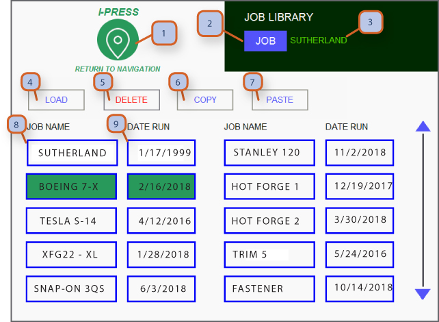
1. NAVIGATION BUTTON: Pressing this takes you to navigation screens. Depending on password level for operator or supervisor, More or less screens are accessible.
2. JOB: Press to go to “job memory” screen.
3. JOB NUMBER: Displays current 10 digit alphanumeric job that is selected.
4. LOAD: After selecting the desired job, press here to load the job to the press. This will change the cams, die monitoring circuits, SPM and all other job related parameters.
5. DELETE: After selecting the desired job, press here to delete a job.
6. COPY: After selecting the desired job, press here to copy a job. This is very helpful if you only want to make small changes I an existing job.
7. PASTE: After coping a job, press here to paste it to a new spot in the job library.
8. JOB NAME: Display of all the names of saved jobs.
9. DATE RUN: Display of the last date the job ran.
Job Memory / Single Point Edit Servo Hydraulic
1. NAVIGATION BUTTON: Pressing this takes you to navigation screens. Depending on password level for operator or supervisor, More or less screens are accessible.
2. CHANGE PASS MODE: Toggle between pressure and position. Pressure mode will make sure your pressure will reach the desired value, and position mode will make sure your position marker is reached regardless of the tonnage.
3. JOB: Press to go to “job memory” screen. You have arrived.
4. JOB NUMBER: Displays current 10 digit alphanumeric job that is selected. -
5. OK MONITOR: Green display shows that all systems are functioning and no faults are present
6. UPDATE RECIPE: After you have set the dm 1 to 16 best suited for the job, and then press return to job memory screen.
7. CYCLE TIME: Displays the total cycle time in seconds.
8. TOGGLE % / IPM: This button toggles between '%' and "IPM". This will change the way the speed of each part of the stroke is Being displayed (#16). '%' = percentage out of max speed - max speed is different for each part of the cycle - change to IPM for More accuracy or refer to machine specs. IPM = inch per minute.
9. FA: Fast approach is used to move the ram at maximum speed from tdc towards BDC before hitting the material.
10. SA: Slow approach - once close to the material, use slow approach for the last couple of inches of the approach before Touching the material.
11. FP1: Fast press 1 is for when the ram comes in contact with the material. Speed of press can be changed to desired value.
12. SP1: Slow press 1 is used for the last part of the downwards stroke for a more accurate and gentle stop.
13. DW: Dwell time is used when you need a dwelling period at the bottom of the stroke.
14. SU: Slow up is used for the initial slow movement upwards after the material has been pressed.
15. FU: Fast up is used to reach tdc at high speed to minimize cycle time.
16. ST: Slow top is used for the last part of the stroke just before tdc.
17. SPEED DISPLAY: This is where the speed of each part of the stroke is displayed.
18. TOP: Press here to programmable your top set point. After pressing, you can set by current position or by entering a distance in Inches from tdc. Red position bar moves according to ram position.
19. BOTTOM: Press here to programmable your bottom set point. After pressing, you can set by current position or by entering a Distance in inches from tdc. Red position bar moves according to ram position.
Performance Monitor / Single Point Edit Servo hydraulic
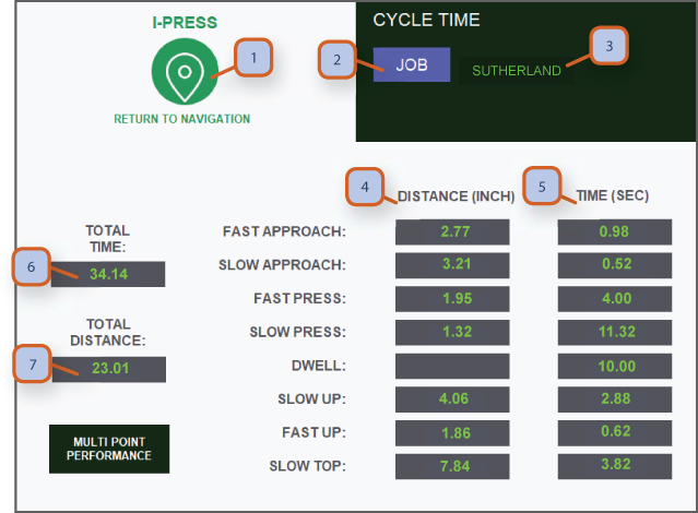
1. NAVIGATION BUTTON: Pressing this takes you to navigation screens. Depending on password level for operator or supervisor, more or less screens are accessible.
2. JOB: Press to go to “job memory” screen.
3. JOB NUMBER: Displays current 10 digit alphanumeric job that is selected.
4. DISTANCE: Displays the distance in inches of each part of the stroke.
5. TIME: Displays the time in seconds of each part of the stroke.
6. TOTAL TIME: Displays total cycle time in seconds.
7. TOTAL DISTANCE: Displays total stroke length in inches.
THIS PAGE IS GREAT FOR CYCLE TIME OPTIMIZATION. IT ALLOWS VIEWING EACH MOTION SECTION OF THE CYCLE "LIVE" AND CHANGING VALUES TO REACH MAXIMUM OUTPUT.
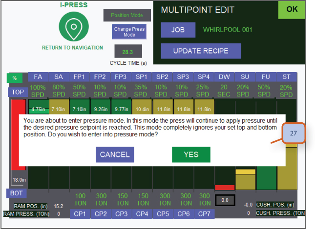
Job Memory / Multi Point Edit Servo Hydraulic
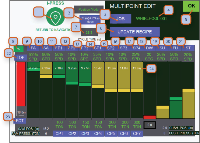
1. NAVIGATION BUTTON: Pressing this takes you to navigation screens. Depending on password level for operator or supervisor, more or less screens are accessible.
2. JOB: Press to go to “job memory” screen.
3. JOB NUMBER: Displays current 10 digit alphanumeric job that is selected.
5. OK MONITOR: Green display shows that all systems are functioning and no faults are present.
6. UPDATE RECIPE: After you have set the dm 1 to 16 best suited for the job, and then press return to job memory screen.
7. CYCLE TIME: Displays the total cycle time in seconds.
8. TOGGLE % / IPM: This button toggles between '%' and "Ipm". This will change the way the speed of each part of the stroke is being displayed. '%' = percentage out of max speed - max speed is different for each part of the cycle - change to ipm for better accuracy or refer to machine specs. Ipm = inch per minute. See screen 9.2- #23 & #24 for more details.
9. FA: Fast approach is used to move the ram at maximum speed from tdc towards bdc before hitting the material.
10. SA: Slow approach - once close to the material, use slow approach for the last couple of inches of the approach before touching the material.
11. FP1: Fast press 1 - is when the ram comes in contact with the material. Speed of press can be changed to desired value.
12. FP2: Fast press 2 - use this cycle if you'd like to press at a different speed than fp1.
13. FP3: Fast press 3 - use this cycle if you'd like to press at a different speed than fp2.
14. SP1: Slow press 1- is used for the last part of the downwards stroke for a more accurate and gentle stop.
15. SP2: Slow press 2 - use this cycle if you'd like to slow press at a different speed than sp1.
16. SP3: Slow press 3 - use this cycle if you'd like to slow press at a different speed than sp2
17. SP4: Slow press 4 - use this cycle if you'd like to slow press at a different speed than sp3
18. DW: Dwell time is used when you need a dwelling period at the bottom of the stroke.
19. SU: Slow up is used for the initial slow movement upwards after the material has been pressed.
20. FU: Fast up is used to reach tdc at high speed to minimize cycle time.
21. ST: Slow top is used for the last part of the stroke just before tdc.
22. TOP: Press here to programmable your top set point. After pressing, you can set by current position or by entering a distance in inches from tdc. Red position bar moves according to ram position.
23. BOTTOM: Press here to programmable your bottom set point. After pressing, you can set by current position or by entering a distance in inches from tdc. Red position bar moves according to ram position.
24. INDIVIDUAL STROKE LENGTH: This number is how many inches from tdc is each part of the stroke.
25. IPM \ INCH PER MINUTE: When IPM is displayed the speed of each part of the stroke will be displayed in IPM.
26. SPEED DISPLAY: This is where the speed for each part of the stroke is displayed.
27. PRESS MODE CHANGE POP UP: This message is a safety step the operator must take in order to change the mode of the press.
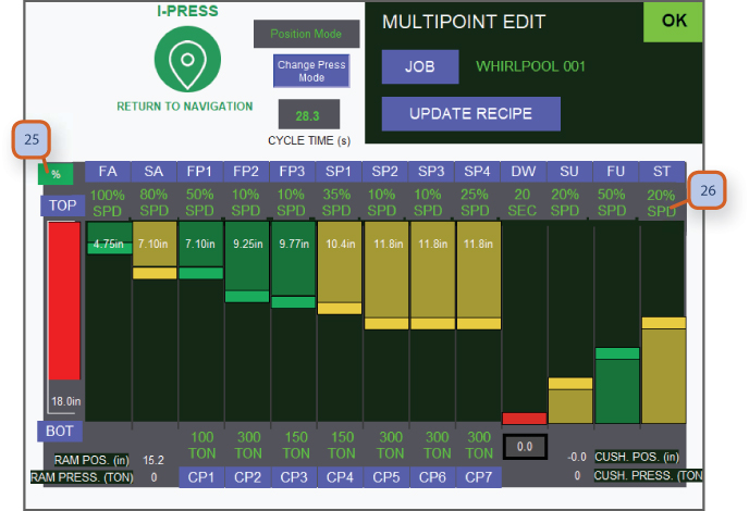
Performance Monitor / Multi Point Edit Servo Hydraulic
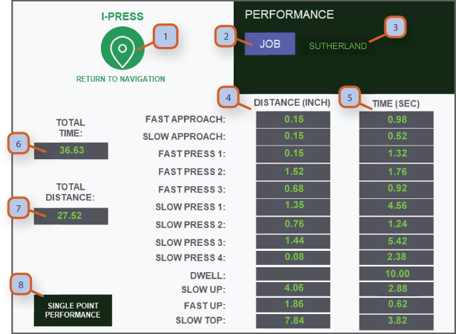
1. NAVIGATION BUTTON: Pressing this takes you to navigation screens. Depending on password level for operator or supervisor, more or less screens are accessible.
2. JOB: Press to go to “job memory” screen.
3. JOB NUMBER: Displays current 10 digit alphanumeric job that is selected.
4. DISTANCE: Displays the distance in inches of each part of the stroke.
5. TIME: Displays the time in seconds of each part of the stroke.
6. TOTAL TIME: Displays total cycle time in seconds.
7. TOTAL DISTANCE: Displays total stroke length in inches.
8. SINGLE POINT PERFORMANCE: Press to go to single point performance page.
Parts Counters / Batch Counters
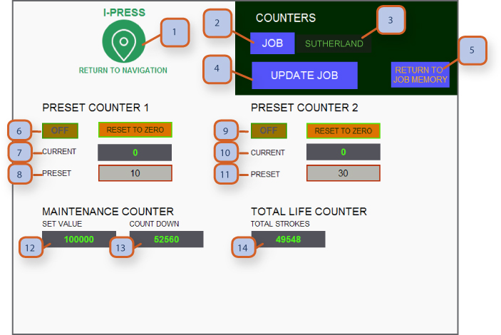
1. NAVIGATION BUTTON: Pressing this takes you to navigation screens. Depending on password level for operator or supervisor, more or less screens are accessible.
2. JOB: Press this button to go to “job memory” screen.
3. JOB NUMBER: Displays current 10 digit alphanumeric job that is selected.
4. UPDATE JOB: After you have set the counters best suited for the job, press save job button.
5. RETURN TO JOB MEMORY: Press blue hot key to return to job memory screen. Once there you can then go on to cams, tonnage & counter screen to complete your job set up and make final save. (follow instructions on job memory screen on the steps for setting up a new job)
6. ON PRESET 1: Toggle on / off or you can press "Reset to zero" to clear fields.
7. CURRENT: Displays the current count on your way to the desired preset value.
8. PRESET: Allows you to enter the desired value of parts to be run before press will stop at batch complete.
9. ON PRESET 2: Toggle on / off or you can press reset to zero to clear fields.
10. CURRENT: Displays the current count on your way to the desired preset value.
11. PRESET: Allows you to enter the desired value of parts to be run before press will stop at batch complete.
12. MAINTENANCE COUNTER SET VALVE: This is set by a supervisor with level 2 password on the maintenance & life counter screen.
13. MAINTENANCE COUNT DOWN: This shows the countdown which is also shown on the main run screen so operator has a head up before maintenance stop.
14. TOTAL LIFE COUNTER: This shows total life count of the press.
Note:
When count reaches 80% of it's value, the display will turn yellow. At 90% it'll turn red. This is so that the operator can be prepared for the machine to stop.
Fault History
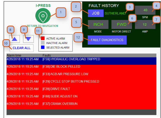
1. NAVIGATION BUTTON: Pressing this takes you to navigation screens. Depending on password level for operator or supervisor, more or less screens are accessible.
2. JOB: Press to go to “job memory” screen.
3. JOB NUMBER: Displays current 10 digit alphanumeric job that is selected.
4. SPM: Display current SPM/ stroke per minute setting.
5. MODE: Displays current position for mode of operation selector switch located at t-stand.
6. MOTOR DIRECTION: Display current direction of main motor, press will only operate in inch when in reverse.
7. AMP: Displays main motor amp draw.
8. SCROLL UP: Click here to scroll up.
9. SCROLL DOWN: Click here to scroll down.
10. CLEAR ALL: Click here to clear all faults. Unresolved faults will remain.
11. LEGEND: This legend is helpful for the operator to understand the different colors of the fault lines below.
12. FAULT DIAGNOSTICS: Press blue hot key will take you to fault diagnostics page, where you can find step by step troubleshooting guidance.
Fault Diagnostics / Step X Step
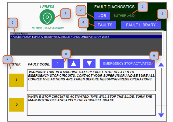
1. NAVIGATION BUTTON: Pressing this takes you to navigation screens. Depending on password level for operator or supervisor, more or less screens are accessible.
2. JOB: Press to go to “job memory” screen.
3. JOB NUMBER: Displays current 10 digit alphanumeric job that is selected.
4. FAULTS: Press this to go to fault history page
5. FAULT LIBRARY: Press this to go to fault library page
6. ACTIVE FAULTS: List of active faults (in most cases, pressing the reset button at the t-stand will clear each fault)
7. DIAGNOSTIC STEPS: Suggestions in sequence for trouble shooting cause of faults
8. FAULT CODE: Displays the fault code of the selected fault
9. FAULT NAME: Displays the name of selected fault
Note:
• In most cases, you can clear faults by pressing the ‘reset” button at the t-stand.
• Only a few faults require supervisor password. (overrun, dual valve reset, maintenance counter & re-zero encoder)
100+ Monitored Faults
SEE FAULT LIBRARY SUBJECT
Fault Library / Fault Grouping
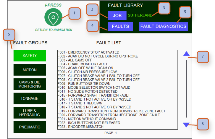
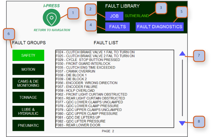
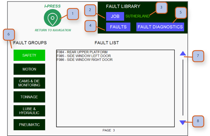
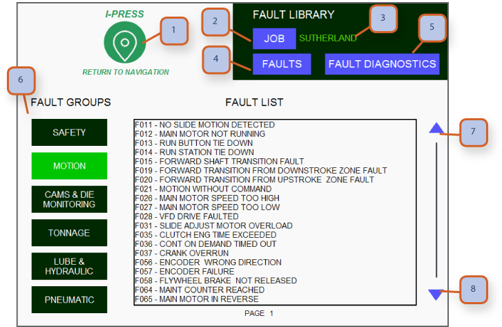
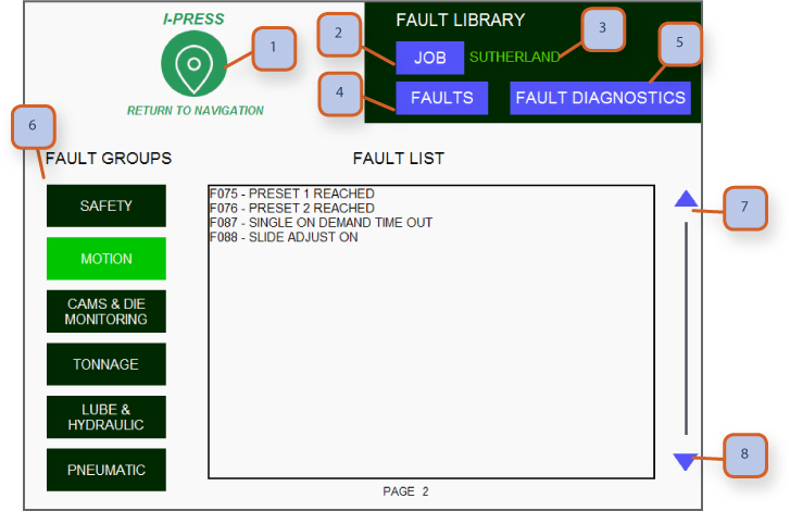
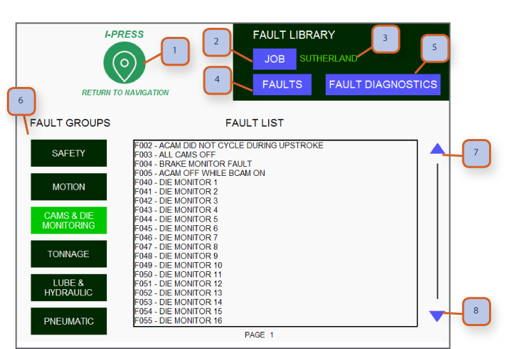
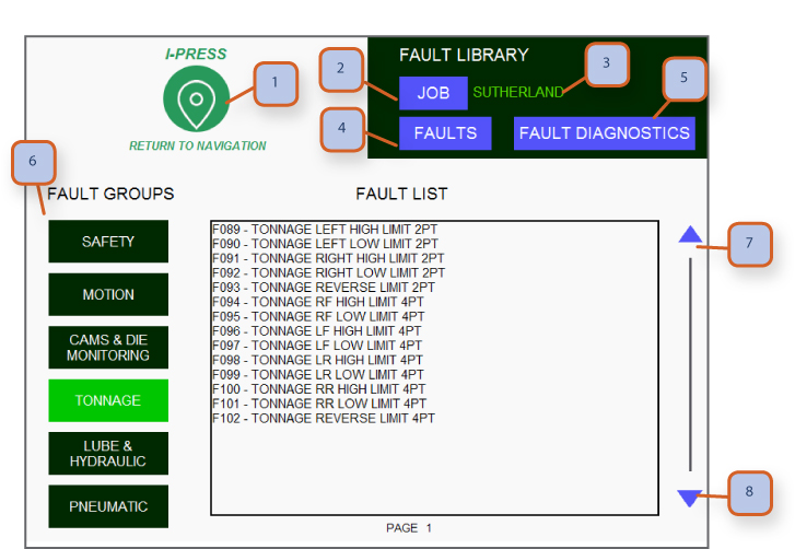
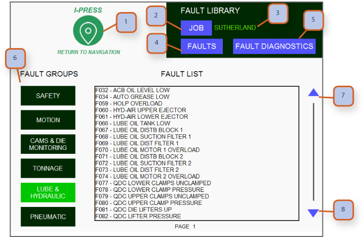
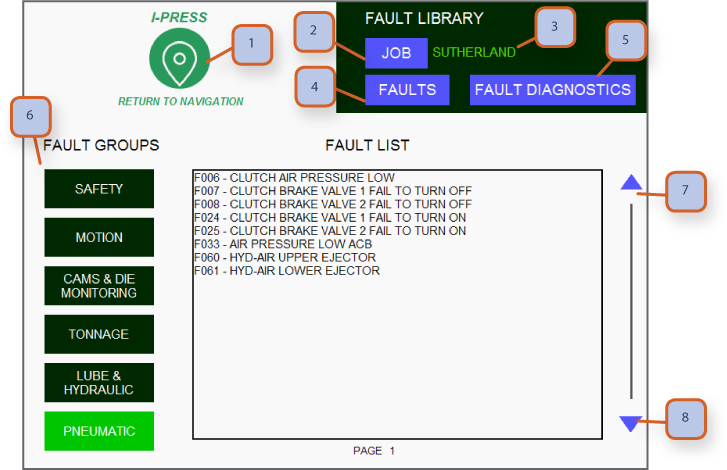
1. NAVIGATION BUTTON: Pressing this takes you to navigation screens. Depending on password level for operator or supervisor, more or less screens are accessible.
2. JOB: Press to go to “job memory” screen.
3. JOB NUMBER: Displays current 10 digit alphanumeric job that is selected.
4. FAULTS: Press here to go to fault history page.
5. FAULT DIAGNOSTICS: Press to go to fault diagnostics page.
6. FAULT GROUPS: Press each of the group names to view the faults in this group.
7. SCROLL UP: Press here to scroll up.
8. SCROLL DOWN: Press here to scroll down.
QDC / Hydraulice Die Lifters
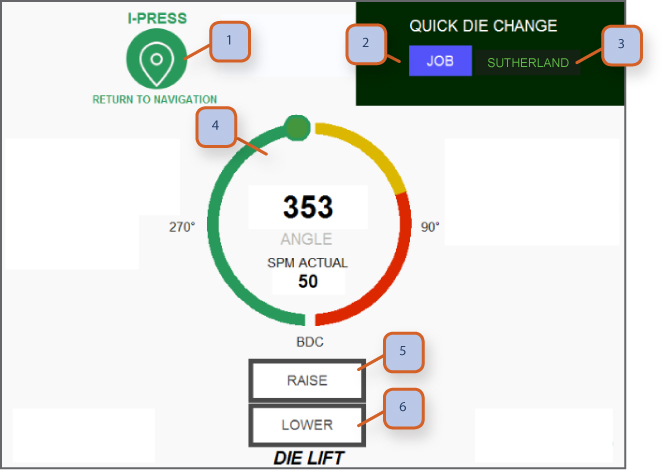
1. NAVIGATION BUTTON: Pressing this takes you to navigation screens. Depending on password level for operator or supervisor, more or less screens are accessible.
2. JOB: Press to go to “job memory” screen.
3. JOB NUMBER: Displays current 10 digit alphanumeric job that is selected.
4. POSITION INDICATOR: Displays current slide position.
5. RAISE: Press to raise hydraulic die lifters, in order to remove/install tooling. **can only be operated at tdc.
6. LOWER: Press to lower hydraulic die lifters. **can only be operated at tdc.
QDC / Quick Die Change
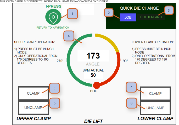
1. NAVIGATION BUTTON: Pressing this takes you to navigation screens. Depending on password level for operator or supervisor, More or less screens are accessible.
2. JOB: Press to go to “job memory” screen.
3. JOB NUMBER: Displays current 10 digit alphanumeric job that is selected.
4. POSITION INDICATOR: Displays current slide position.
5. UPPER CLAMP- CLAMP: Press to energize upper clamps. **can only be pressed at bdc**
6. UPPER CLAMP - UNCLAMP: Press to de-energize upper clamps. **can only be pressed at bdc**
7. LOWER CLAMP - CLAMP: Press to energize lower clamps. **can only be pressed at bdc**
8. LOWER CLAMP - UNCLAMP: Press to de-energize lower clamps. **can only be pressed at bdc**
Lubrication Grease Type
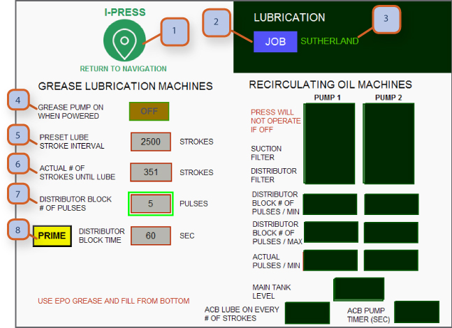
1. NAVIGATION BUTTON: Pressing this takes you to navigation screens. Depending on password level for operator or supervisor, more or less screens are accessible.
2. JOB: Press to go to “job memory” screen.
3. JOB NUMBER: Displays current 10 digit alphanumeric job that is selected.
Note: When your machine is set up at the factory, type of lube system, grease or recirculating oil is selected so you will only have access to adjust the lube system that fits your press. Only the active lube system will be displayed on the hmi screen.
Grease Lubrication System
4. GREASE PUMP: Press this to toggle on/off, when this is on, each time the press is started up, grease pump will make a full cycle. If presses are turned on/off a lot during a day, this should be in the off position. With system in off, grease pump will only cycle on a set number of stroke.
5. PRESET LUBE STROKE INTERVAL: Lubrication pump will turn on every # of strokes, this is your key setting point. Depending on speed, single stroke or continuous modes of operation you may need more or less lube. Watch the grease collection trays and grease on crankshaft, if you are getting excessive grease, increase the # of strokes, between lube intervals. A good starting point is 3000 strokes.
6. ACTUAL # OF STROKES UNTIL LUBE: Stroke countdown until lube pump is initiated.
7. DISTRIBUTOR BLOCK # OF PULSES: Distributor block has an electronically monitored cycle pin. Should the grease pump run low, this will detect lack of flow and show low grease on hmi screen.
8. PRIME: Press the yellow prime button to manually prime the lube system and the grease pump will run for the time set on #7.
Lubrication Recirculating Oil Type
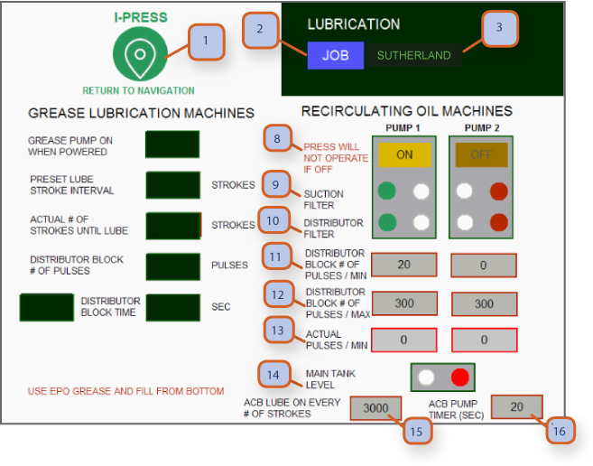
1. NAVIGATION BUTTON: Pressing this takes you to navigation screens. Depending on password level for operator or supervisor, more or less screens are accessible.
2. JOB: Press to go to “job memory” screen.
3. JOB NUMBER: Displays current 10 digit alphanumeric job that is selected.
Note: When your machine is set up at the factory, type of lube system, grease or recirculating oil is selected so you will only have access to adjust the lube system that fits your press. Only the active lube system will be displayed on the hmi screen. (both lube systems are shown here for instructions only)
Recirculating Oil System (for larger straight side presses)
8. PUMP OFF/ON: Indicates current status of oil pump.
9. SUCTION FILTER: This will show green when operating correctly and red when filter is plugged & requires cleaning.
10. DISTRIBUTOR FILTER: This will show green when operating correctly and red when filter is plugged & requires cleaning.
11. DISTRIBUTOR BLOCK # OF PULSES / MIN: Refer to lubrication schematic for minimum setting for cycle pin at distributor block.
12. DISTRIBUTOR BLOCK # OF PULSES / MAX: Refer to lubrication schematic for maximum setting for cycle pin at distributor block.
13. ACTUAL PULSES / MIN: Displays actual number of pulses per minute.
14. MAIN TANK LEVEL: Main oil tank is equipped with a low level sensor, green is operational & red is low level & fault will show on hmi screen.
15. ACB LUBE ON EVERY # STROKES: You can set the # of strokes to activate acb / air counter balance oiler.
16. ACB PUMP TIMER SECONDS: You can set the # of seconds for the acb / air counter balance oiler to complete it's cycle.
Light Curtain Safety Mute On Upstroke
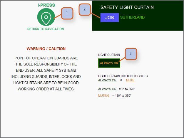
1. NAVIGATION BUTTON: Pressing this takes you to navigation screens. Depending on password level for operator or supervisor, more or less screens are accessible.
2. JOB: Press to go to “job memory” screen.
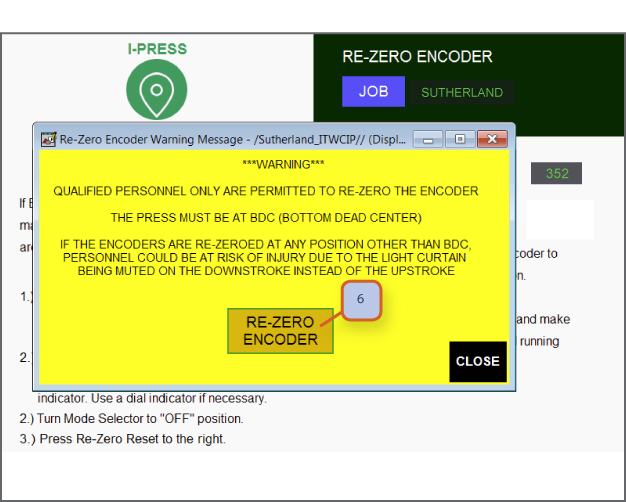
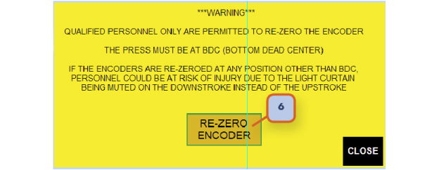
3. LIGHT CURTAIN: Allows you to toggle between always on or mute on up stroke. Caution: when you re-zero encoder & actual slide position, you will get a warning screen warning you be to sure re-zero process is accurate. We encourage that you select light curtains always on during re-zero of encoder and then test the system before going back to mute on up stroke.
Note: Point of operation guards are the sole responsibility of the end user. Operators are to report any guards or light curtains that are not in good working order.
Maintenance Counter
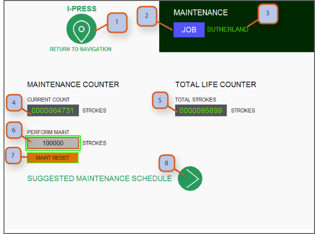
1. NAVIGATION BUTTON: Pressing this takes you to navigation screens. Depending on password level for operator or supervisor, more or less screens are accessible.
2. JOB: Press to go to “job memory” screen.
3. JOB NUMBER: Displays current 10 digit alphanumeric job that is selected.
4. MAINTENANCE CURRENT COUNT: Displays current count up to when perform maintenance stop will occur. This also shows on the lower right of main run screen and is shown with counter counting down to 0-zero so operator can see when maintenance stop is about to occur.
5. TOTAL STROKES: This is a total life counter.
6. PERFORM MAINTENANCE: Supervisor can preset number for maintenance stop. The press will stop after this preset number of strokes.
7. MAINT. RESET: Press to reset the maintenance counter.
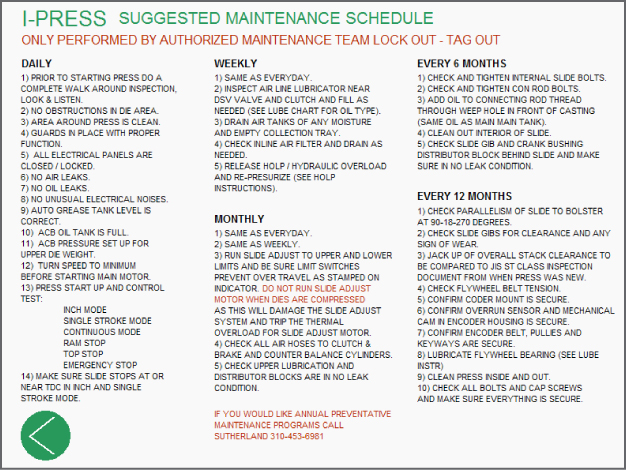
8. SCROLL: Press to view suggested maintenance to optimize up time on your press.
Special Modes Of Operation
1. NAVIGATION BUTTON: Pressing this takes you to navigation screens. Depending on password level for operator or supervisor, more or less screens are accessible.
2. JOB: Press to go to “job memory” screen.
3. LIGHT CURTAIN: Allows you to toggle between always on or mute on up stroke. Caution: when you re-zero encoder & actual slide position, you will get a warning screen warning you be to sure re-zero process is accurate. We encourage that you select light curtains always on during re-zero of encoder and then test the system before going back to mute on up stroke.
Note: Point of operation guards are the sole responsibility of the end user. Operators are to report any guards or light curtains that are not in good working order.
Clutch Brake Valve Reset
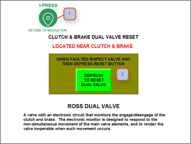
1. NAVIGATION BUTTON: Pressing this takes you to navigation screens. Depending on password level for operator or supervisor, more or less screens are accessible.
2. PRESS TO RESET: This will reset the DSV safety valve for clutch & brake.
Note:
• DSV valve and air systems must be properly maintained for optimum operation.
• Air tank and all press air supply lines should be drained weekly to remove any moisture build up.
• We encourage you to add collection lines & devices to keep press and area clean & collect any moisture or oil build up.
• Inspect and clean exhaust muffler on DSV valve, restricted air exhaust will reduce brake stopping time.
Overrun Reset
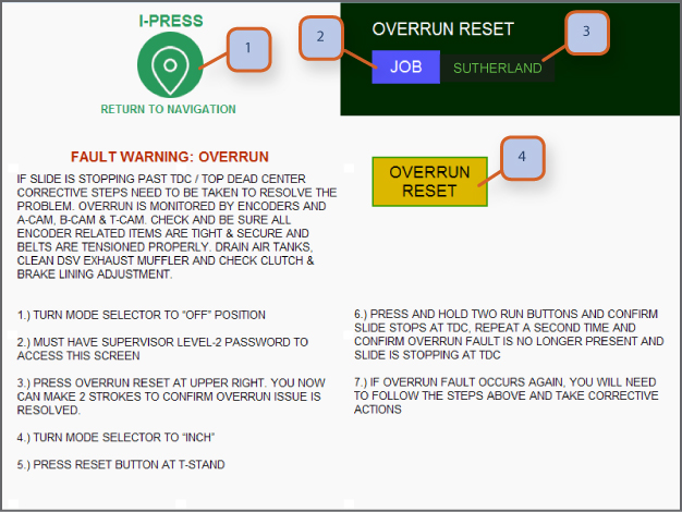
Note:
**follow on screen instructions**
1. NAVIGATION BUTTON: Pressing this takes you to navigation screens. Depending on password level for operator or supervisor, more or less screens are accessible.
2. JOB: Press to go to “job memory” screen.
3. JOB NUMBER: Displays current 10 digit alphanumeric job that is selected.
4. OVERRUN RESET: Press to start overrun reset sequence.
Re-Zero Encoder
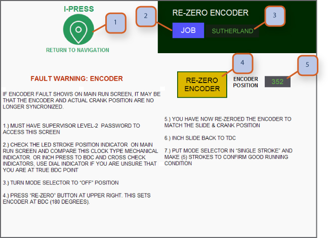
1. NAVIGATION BUTTON: Pressing this takes you to navigation screens. Depending on password level for operator or supervisor, more or less screens are accessible.
2. JOB: Press to go to “job memory” screen.
3. JOB NUMBER: Displays current 10 digit alphanumeric job that is selected.
4. RE-ZERO ENCODER: Press to re-calibrate encoder (once pressed a yellow warning screen will show to ensure safety). This calibrates the encoder at 180 degree.
5. ENCODER POSITION: Displays current encoder position in degrees.
6. RE-ZERO ENCODER: Press to re-calibrate encoder. Follow on screen instructions.
Feature Sets / Other Call Options
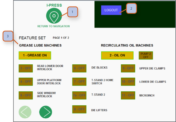
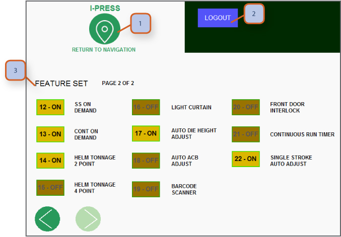
1. NAVIGATION BUTTON: Pressing this takes you to navigation screens. Depending on password level for operator or supervisor, more or less screens are accessible.
2. LOGOUT: This allows users to logout so other can login with their password level.
3. FEATURE SETS TOGGLE: This section allows a certified SP technician only to toggle feature sets on or off.


2.jpeg)
.png)


